Galaxy 3 Series Installation Manual
2-3
On-board RIOs/ Smart PSUs/EN51 PSU Keypads Keyprox MAX
Galaxy Panel Zones Outputs Poss. Address Zones Outputs Poss. Address Poss. Address Poss.
520 (line 1)
(lines 2, 3, 4)
16 8 15
16
1 - 9, A - F
0 - 9, A - F
120
384
60
64
8
8
0 - 2, B, C, D, E, F
0 - 6, F
3
7
0-2
0-6
8
8
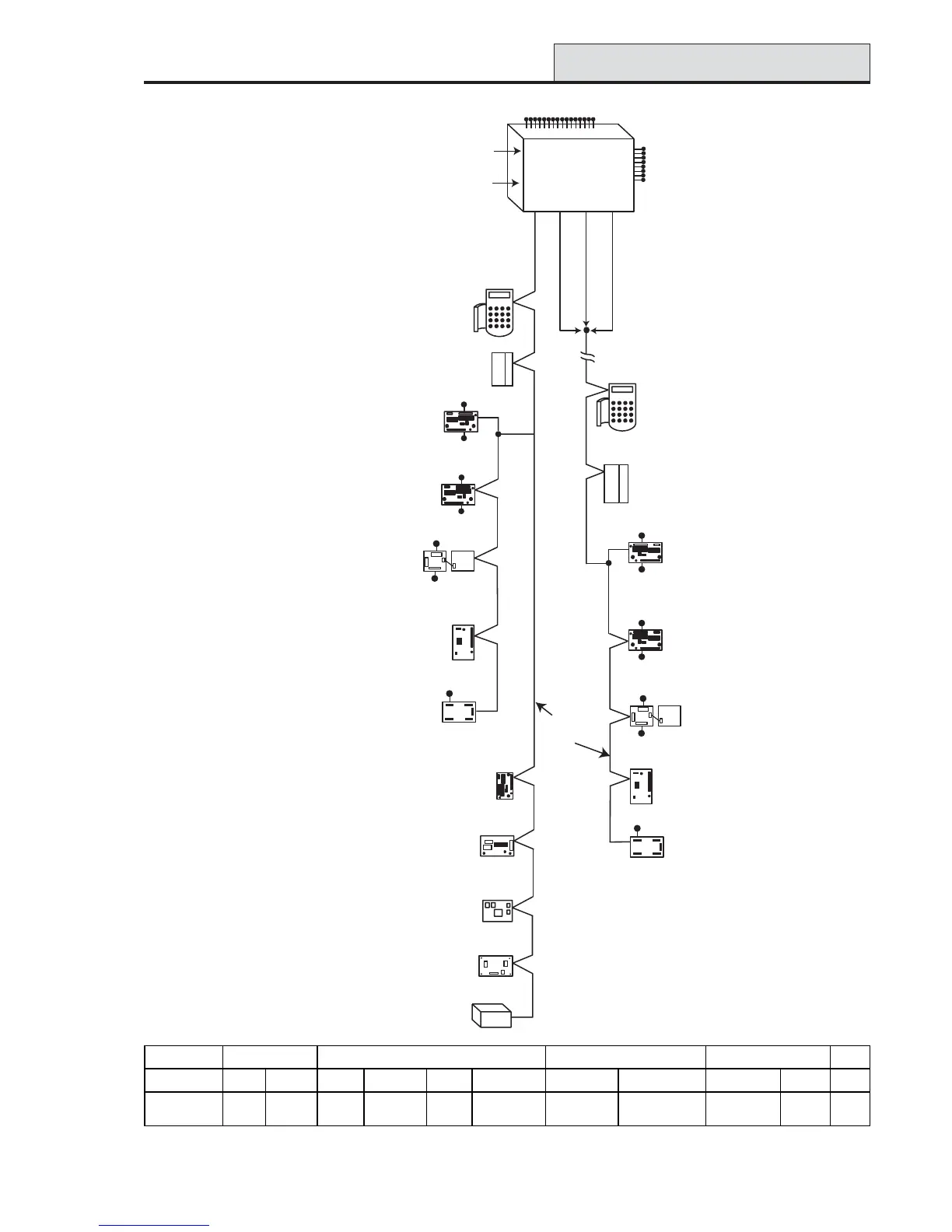
Figure 2-3. Galaxy 3-520 System Configuration
G3-520 Configuration
Galaxy 3-520
Line Line Line Line
1234
K
eypads (8)
CP027/
Keyprox (3)
CP028
Max (8)
MX03
Keypads (8)
CP027/
Keyprox (7)
CP028
8 zones
4 outputs
RIO (15)
C072
8 zones
4 outputs
OR
8 zones
4 outputs
8 zones
4 outputs
Smart PSU (16)
P015
RIO (16)
C072
Twisted Pair
Screened Cable
W002
Cable run 1 km (max)
Cable run 1 km (max)
Lines 2, 3 and 4 have the same configuration
RF RIO Module (16)
C076
Certain keypad and
max addresses can
be replaced by a
combined keyprox unit.
*
*
*
*
*
NOTE:
Valid addresses for the
keyprox are:
Line 1 (0, 1 & 2).
Lines 2, 3 & 4 (0-6).
This sets the address for both
the keypad and card reader
parts of the keyprox.
16 zones on board
8 outputs
on board
on board
telecom
area
Max (8)
MX03
OR
OR
OR
OR
OR
NOTE:
RIOs, RF RIO's and
PSU's can be mixed on
the lines. The maximum
number of combined
modules is given in the
table below.
*
RS232
Serial Port
PSTN
8 zones
4 outputs
Power Unit (16) P025
or
Power RIO (16) P026
Smart PSU (15)
P015
8 zones
4 outputs
RF RIO Module (15)
C076
Power Unit (15) P025
or
Power RIO (15) P026
Printer Interface (1)
A134/A161
ISDN Module (1)
E077 (comm 3)
RS232 Module (1)
E054 (comm 2)
Telecom Module (1)
E062 (comm 5)
Ethernet Module (1)
E080 (comm 4)
Output Module (4)
C078
4 - 16 outputs
Output Module (4) C078
NOTE: Each Output Module can simulate
up to 4 RIO's (outputs only) depending
on DIP switch setting.
Valid addresses for the Output Module are
the same as standard RIO's.
4 - 16 outputs
NOTE:
The Telecom, Printer Interface,
RS232, Ethernet and ISDN
modules can only be
connected to line 1.
If a Telecom module is attached,
keypad address E cannot be
connected to line 1(address E is
shown as 18 on the system).
If an RS232 module is attached,
keypad address D cannot be
connected to line 1 (address D is
shown as 17 on the system).
If an Ethernet module is attached,
keypad address B cannot be
connected to line 1 (address B is
shown as 15 on the system).
If an ISDN module is attached,
keypad address C cannot be
connected to line 1 (address C is
shown as 16 on the system).

 Loading...


