Galaxy 3 Series Installation Manual
B-1
Appendix B: 3 Ampere Smart PSU - P015
Smart PSU
The Galaxy Smart PSU can be connected to the Galaxy control panels. The Smart PSU integrates a three
ampere power supply with an eight zone Galaxy RIO. This can be used in place of a standard RIO to over-
come power problems that arise when the additional RIO is fitted distant to the control panel.
The connection, addressing, zones and outputs information is identical to that described in the previous Re-
mote Input Output (RIO) Modules sub-section.
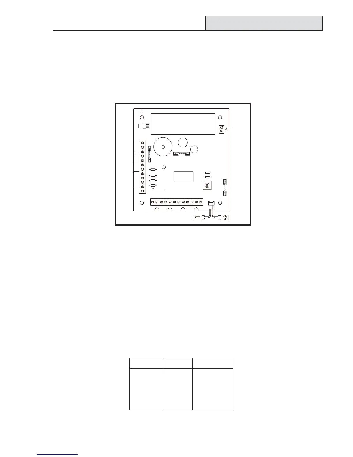
Figure B-1. Galaxy 3A Smart PSU
NOTE: The number of pull-up resistors may vary with different hardware revisions.
Grounding
The 0V on the Galaxy system is connected to earth via mounting screws on the Smart PSU. The 0V must be
connected to earth at the main control panel only. If a smart PSU is being used remotely, an insulating washer
should be fitted behind the head of the top left mounting screw.
The integrated RIO has eight programmable zones and four programmable outputs. It is programmed and
operates in exactly the same way as the standard Galaxy RIO. The Smart PSU has two separately fused
regulated 12 Vd.c. outputs, each capable of supplying one ampere to additional modules and devices. A
fused regulated voltage is also supplied to charge a 12 volt lead-acid stand-by battery.
For further information refer to Galaxy Smart Power Supply Unit Installation Instructions (II1-0101).
The default functions and pull-up resistors of each Smart PSU output, when connected to a Galaxy are shown
in the following Table:
Table B-1. Smart PSU Output Default Functions
NOTE: The number of pull-up resistors may vary with different hardware revisions.
.oNtuptuOnoitcnuFrotsiseRpu-lluP
1slleB34R
2ebortS73R
3AP33R
4teseR32R
1 1/2 2
3
3/4
4
5
5/6
6
7
7/8
8
Zones 1-8
S1
+
-
A
B
A
B
T
-
+
12V2
-
+
12V1
4
3
21
O/P
HEATSINK
-
+
F4 (1.6 A)
F3 (1.6 A)
Batt F2
(2.5 A)
PROCESSOR
LED
3k3Ω pull-up
resistors
AC
Connector
Comms
Line
Tamper
Outputs
Rotary
Address
Switch
LK2
LK3
Comms
Socket
R23
R33
R37
R43
Rev 0.8

 Loading...


