Rev. 1.01 9 900.0570
8-Sept-05
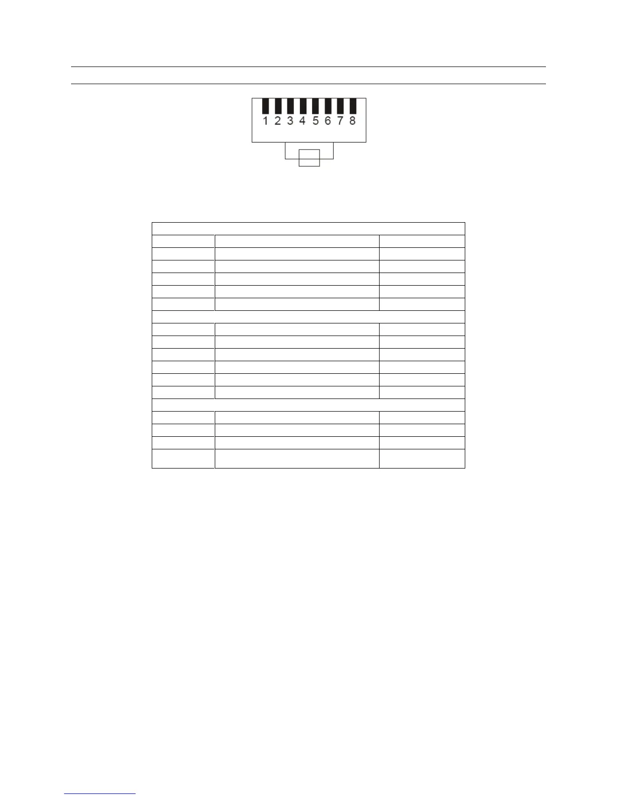
2.6 CONNECTOR PIN ASSIGNMENTS
Viewed from wiring input side of plug
Figure 2. KBD/AUX/CONTROL CONNECTORS
KBD
Pin Signal Usual colour
1 To slave D+ White / Orange
2 To slave D- Orange
4 From slave or VCL data in D- Blue
5 GND White / Blue
6 From slave or VCL data in D+ Green
AUX
Pin Signal Usual colour
1 From master D+ White / Orange
2 From master D- Orange
4 To DVR or master D- Blue
5 GND White / Blue
6 To DVR or master D+ Green
CONTROL
Pin Signal Usual colour
1 To / from dome D+ White / Orange
2 To / from dome D- Orange
3 GND White / Green

 Loading...