Maintenance
UsermanualforHONR100gaspressureregulatorwithHONP095NGpilot 60
Figure Step Description
39
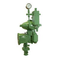
Putthedomebackinplace.Tightenthe
nuts (1)inacriss‐crosssequence.
Observethetighteningtorqueinformation
providedinthetablebeforethissection.
Proceedasfollows:
Figure Step Description
1
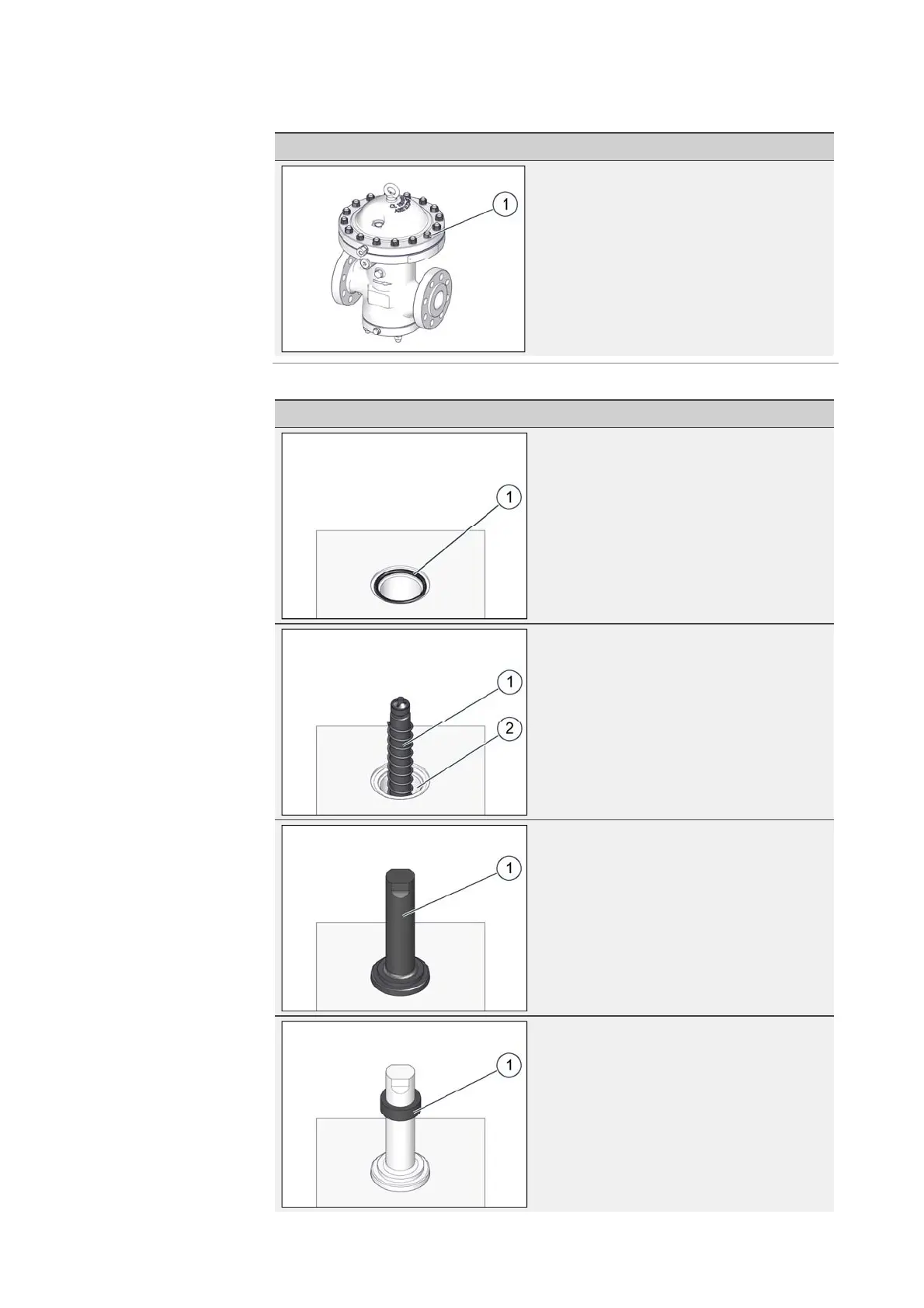
ReplacetheO‐ring(1)inthebodyhole
intendedforthepositionindicatorwitha
new,greasedO‐ring.
2
Inserttheinnerpin,includingthespring
(1),backintothehole(2)fortheposition
indicator.
3
Useanopen‐endwrenchtoscrewthe
positionindicator’shousing(1)backin
place.
4
Pullthemagneticring(1)overtheposition
indicator’shousing.Themagneticring
positionshowninthefiguretotheleft
showsthecorrectinstallationheight.
Maintainingandin‐
stallingtheposition
indicator

 Loading...