Ù»¾® «·µ-¿ ¿²©·¶¦·²¹ ó Ò» ¼»®´¿²¼-
45
MIGHTEVAC MET BEVESTIG-
INGSBEUGEL
5.2 Installatie van MightEvac op de
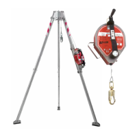
5.0 Installatie
5.1 Algemeen Installatie en het tot stand bren-
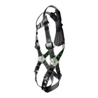
Voor de valbeveiliging als zodanig verbindt u de
een veerhaak) aan de D-ring op de rug van het
volledige lichaamsharnas
-
jn moet met behulp van een karabijnhaak of een
andere, door Miller goedgekeurde, verankering-
skoppeling, met de roterende bevestigingswartel
aan een verankering boven het hoofd worden
combinatie met een Miller bevestigingsbeugel,
die vervolgens op een driepoot. De verankerin-
gen moeten in staat zijn om 22,2 kN (5000 lb)
elastische belasting. Lees alle waarschuwingen
en instructies wanneer u een bevestigingslocatie
bepaalt.
VERANKERINGS-
KOPPELING
KARABIJNHAAK MET
VERGRENDELING
VERANKERING
MAY RESULT IN SERIOUS OR FATAL INJURY
WARNING! FAILURE TO OBSERVE INSTRUCTIONS
PAT. NO. 5,771,993
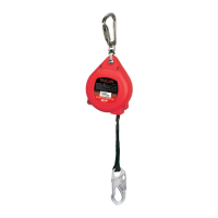
SELF-RET RAC TING LIFELI NE WI TH EME RGE NCY RE SCUE
®
• Always use and inspect unit in accordance
with manufacturer’s instructions.
• Do not use as a restraint or positioning
device.
• Use only with attachment fittings and safety
harness recommended by manufacture r.
• Always connect the hook directly to
attachment point on harness.
• Guard against swing falls by keeping the
lifeline vertically overhead. Never work
above the device.
• Keep user and other workers from becoming
entangled in lifeline.
• Do not allow lifeline to drag over
obstructions.
• Never clamp off or stand on the lifeline.
• Do not allow the lifeline to become slack.
• Do not allow cable, rope or webbing
lifelines to come in contact with anythin g
that will damage the lifeline including, but
not limited to, sharp, abrasive, rough or
high-temperature surfaces, welding, he at
sources, electrical hazards, or moving
machinery.
• Wear gloves when inspecting or handling
cable lifelines.
• Check lifeline for damage, frays, or cuts that
will reduce the strength.
• Maintain tension on the lifeline while letting
it retract after disconnecting from wo rker.
• Servicing must only be performed by the
manufacturer or an approved agent.
WARNI NG: Ma nufacturer ’s instru ctions supplied with t his pro duct at t ime of shipme nt must be foll owed: Failure t o do so could resul t in seriou s
injury o r death. Only for use by ONE person as a pers onal fall arrester. Device m ust b e taken out of servic e for ins pectio n and recertif ication
after arres ting a fa ll or when the imp act indicat or h as been ac tivated. Contact Miller Fall Protec tion if in struc tion manu al is ne eded.
ADVE RTENC IA: Deb en seguir se los instrucc iones del fabri cate pro vistas co n este producto al mome nto de d espach o: El no ha cerio
pued e resu ltar en les iones gr aves o la muert e. Sol o par a el uso po r UNA S OLA per sona co ma de tentor pe rsonal c ontra c aidas. El
dispos itivo d ebe retir arse d el servi cio pa ra ser in specc ionado y recer tificati on lue go de hab er deten ido una caida o cuand o se ha ya
activa do el indi cator de im pacto. Si se req uiere el manual d e instruc ciones consu lte con M iller Fa ll Prote ction.
ADVE RTISSEM EN T: Vou s devez respecter les i nstruct ions d u fabrican t que vo us avez recues avec le produit : Dans le cas
contrai re, vou s risque z de bles sures graves ou meme lamort. Utiliser seule ment pa r UNE pe rsonne co mme arr et de chute
person nelle. L’appareil doit etre mi s hors d ’utilisation p our insp ection et rec ertificati on apres avoir arrete un e chut e ou
lorsq ue l’indicateu r d’imp act a et e active. Co ntactez Miller F all Prot ection si vous av ez besoi n d’un nouvea u man uel.
LB388
Rev. D
MFP9350111
BEVESTIGING-
SWARTEL
Fig. 1
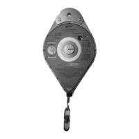
Stap 1: Verwijder de rode, ronde beschermende stickers van beide zijden van het MightEvac-toestel.
Stap 2: Steek de bevestigingswartel van het toestel zoals afgebeeld in de beugel.
Stap 3: Schuif het toestel naar voren totdat de schroefraadopeningen in de behuizing (waar u de stick-
ers van hebt verwijderd) in lijn zijn met de openingen aan de voorzijde van de beugel zoals
afgebeeld.
OPMERKING: De draagbeugel van het toestel moet naar boven staan, van de bevestigingsbeugel af
gekeerd.
Steek de bevestigingsbout door de opening-
sring, vulring en de opening in de
bevestigingsbeugel. Draai de bout aan
tot 10,85 plus of min 1,36 Nm (8 plus
of min één (1) ft-lb = 96 plus of min 12
in-lb). Herhaal dit voor de andere kant.
Stap 4: Steek de pen door de beugel in de aan-
wezige openingen. Hiermee wordt het
Zorg ervoor dat de pen goed door
beide openingen is gestoken en op zijn
plaats blijft.
Stap 5: Bevestig het toestel met de beugel
aan een door Miller goedgekeurd verankeringsvoorziening en zet het met de erbij geleverde
pennen vast. Zie ook de installatieprocedures in de onderdelen 5.3, 5.4, 5.5, 5.6 en 5.7 van dit
handboek.
Om het toestel te verwijderen voert u de stappen in omgekeerde richting uit.
 Loading...