ID2000 Series Installation & Commissioning Manual
Installation - Panel Electronics
22997-433-000-5, Issue 5
May 2010
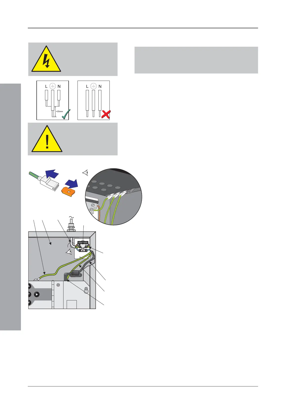
When terminating mains
leads, ensure that the
earth lead is longer than L
and N.
WARNING!
Isolate mains power
before proceeding.
5.2.1.2 Mains and Safety Earth Wiring
Connections
WARNING: Before proceeding, refer to the cabling
instructions given in Section 3.1. Isolate
mains power. Note that fuse information is
given in Appendix 1 Section 1.2.
TRANSIT CABLE CLIP: Before proceeding, CAREFULLY
cut the cable clip that secures the ferrite cable loop to
the front of the back box. DO NOT cut the cable clip that
secures the mains cable to the side of the back box.
The 230V ac mains input wiring (A) must be terminated
at the fused mains termination block (B), located in the
top right-hand corner of the ID2000 Series back box (C).
The PSU mains cable (D) is factory-fitted to the
termination block. Push the mains cable’s connector (E)
into the socket at the top of the PSU3A. Pull tight the
cable clip at the side of the back box.
The safety earth is provided via a short factory-fitted
lead (F) from the mains termination block to a blade
connector at the right rear corner of the back box roof.
All blade connections to earth incorporate a locking barb.
To make a connection push the shrouded receptacle on
to the earth blade (1). To remove this connection, pull
the shroud (2), NOT the earth wire.
Using the wiring provided, make the following two earth
connections:
a. Between the PSU top plate and the back box (G).
b. Between the main chassis and the back box (H).
Connection to the batteries is made using the supplied
battery leads, which may have to be cut to the correct
length. Connection of the batteries (and thermistor) is made
at a four-way socket mounted close to the bottom of the
PSU assembly. Access is gained from underneath the PSU
once the main chassis is fitted to the back box.
For more information on connecting the batteries refer
to Section 8.5, Batteries.
230 VAC,
50 Hz
MF: 5A (T) 250V HRC
230V (a.c.), 5A
VIEW
X
'X'

 Loading...


