EasyManuals Logo

Honeywell Notifier NFG-8 User Manual

Honeywell Notifier NFG-8
54 pages
To Next Page IconTo Next Page
To Previous Page IconTo Previous Page
Page #10 background imageLoading...
Page #10 background image
NFG-8
NFG-8_manu-inst_ITA
Installation and Operation
Manual Doc. M-040.1-NFG8-EN
Rev A.3
PAGE - 11
NOTIFIER ITALY
JP64
CONNECTOR 8 INPUTS
ONLY 4-20mA
JP77
24V POWER SUPPLY FOR
GAS SENSORS
5 2 6 3 7 4 8
9
13
14
10
15
11
12
2.2)
Detector connection
The detectors with 4-20 mA analog output are connected to the control unit, directly on the main
board. For connection, the detector with 4-20 mA analog output requires a 3-conductor cable; 2
conductors for the power supply and one conductor for the 4-20 mA signal. The typical cable
suggested is a 3 x 0.75 shielded cable that allows to reach a distance up to 100 mt between the
gas detector and the control unit.
Wiring diagram 8 7 6 5 4 3 2 1 - - + +
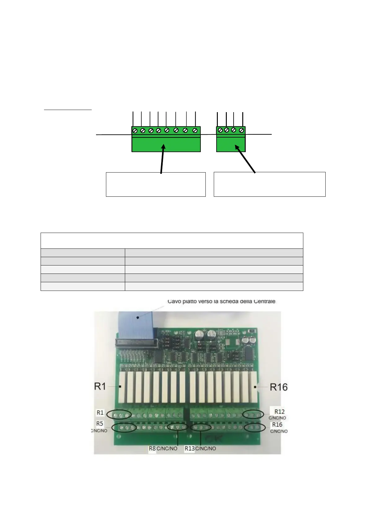
NFG-16REL : 16 relay board (optional)
Technical specifications
Get out:
16 relays contacts capacity 6 A - 250 Vac
Operating temp:
0 ÷ 55°C
Storage temp:
-20 ÷ +60 C°
RH operation:
15 ÷ 85%
RH storage:
5 ÷ 85% (not condensing)
Fig. 2-5) Card layout 16 relays

Questions and Answers:

Question and Answer IconNeed help?

Do you have a question about the Honeywell Notifier NFG-8 and is the answer not in the manual?

Honeywell Notifier NFG-8 Specifications

General IconGeneral
BrandHoneywell
ModelNotifier NFG-8
CategoryControl Unit
LanguageEnglish

Related product manuals