18 UDACT Instruction Manual — P/N 50050:M 12/18/2009
Installation and Wiring Installation
Internal Installation
CHS-4/CHS-4MB Chassis Mounting
(The CHS-4MB consists of the CHS-4N chassis and the MP-1B dress plate.)
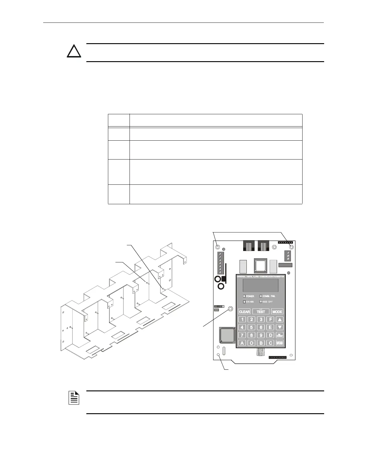
The UDACT is installed on a CHS-4/CHS-4MB Chassis within the control panel backbox as
described and shown below:
!
CAUTION: Remove all power from the control panel by disconnecting AC and batteries before
installation or making any connections to prevent personal and/or circuit damage.
Step Action
1 Disconnect AC power and disconnect batteries.
2 Snap three (3) nylon support posts in the three (3) mounting holes of the
UDACT as shown below.
3 Install one aluminum/nylon standoff and one aluminum standoff onto the studs
of the chassis slot in which the UDACT is to be installed.
Tighten securely.
4 Position the UDACT on the standoffs, snap into place and secure at aluminum
standoff with a #6-32 screw. Tighten securely.
NOTE: These instructions are for mounting the UDACT in a rear position of the CHS-4/CHS-4MB. The board
must then be grounded using a grounding wire connected from the TB3 EARTH terminal to the nearest standoff
connecting the chassis to the cabinet. Do not mount the UDACT in a front position of the CHS-4.
UDACT-21.cdr
Nylon Support Post
Nylon Support
Posts
Aluminum
Standoff
Aluminum/Nylon
Standoff
CHS-4/CHS-4MB
Securing Location
Figure 2.1 CHS-4/CHS-4MB Installation

 Loading...