76 UDACT Instruction Manual — P/N 50050:M 12/18/2009
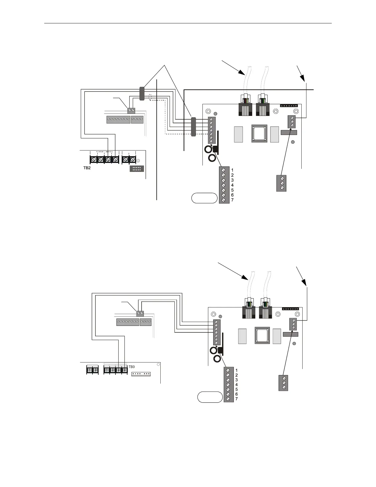
System 5000 (UL 8th) Wiring
Below is a remote installation of a UDACT with a System 5000 using an MPS-24B power supply:
Figure D.1 UDACT and System 5000 with MPS-24B
Below is an internal installation of a UDACT with a System 5000 using an MPS-24A power
supply:
Figure D.2 UDACT and System 5000 with MPS-24A
EARTH
Comm FAILURE
+24V
+24V
GND
RS+
RS–
SHIELD
RS+
Rs–
ACS/TERM
TERM
COMMONCOMMON
BATT -
+24V POWER+24V RES ET
BATT +
UDACT-12.cdr
Solid Earth
Ground
Connection
To Phone Lines
(supervised)
System 5000 Cabinet
System 5000
CPU
EIA-485
Interface
DO NOT USE
MPS-24B
Ferrite Cores
ABS-8RB or UBS-1
EARTH
Comm FAILURE
+24V
+24V
GND
RS+
RS–
SHIELD
RS+
Rs–
ACS/TERM
TERM
+24R COMMO N + 24
COMMON
POWER LIMI TED
BAT + B AT -
UDACT-11.cdr
To Phone Lines
(supervised)
MPS-24A
EIA-485
Interface
DO NOT USE
Connect to CHS-4
Chassis
System 5000
CPU

 Loading...