Communication Card Wiring
January 09 UDA2182 Communications User Guide 3
2. Communication Card Wiring
2.1 Overview
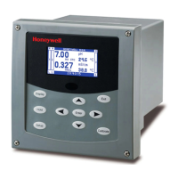
The Communications Card provides one Serial Port and one Ethernet Port. It is installed in the slot next to
the Power Supply Board.
Power Supply Board Communications Card
Ethernet Port
RS485 Port
Power Supply Board Communications Card
Ethernet Port
RS485 Port
Figure 2-1 Communication Card Location
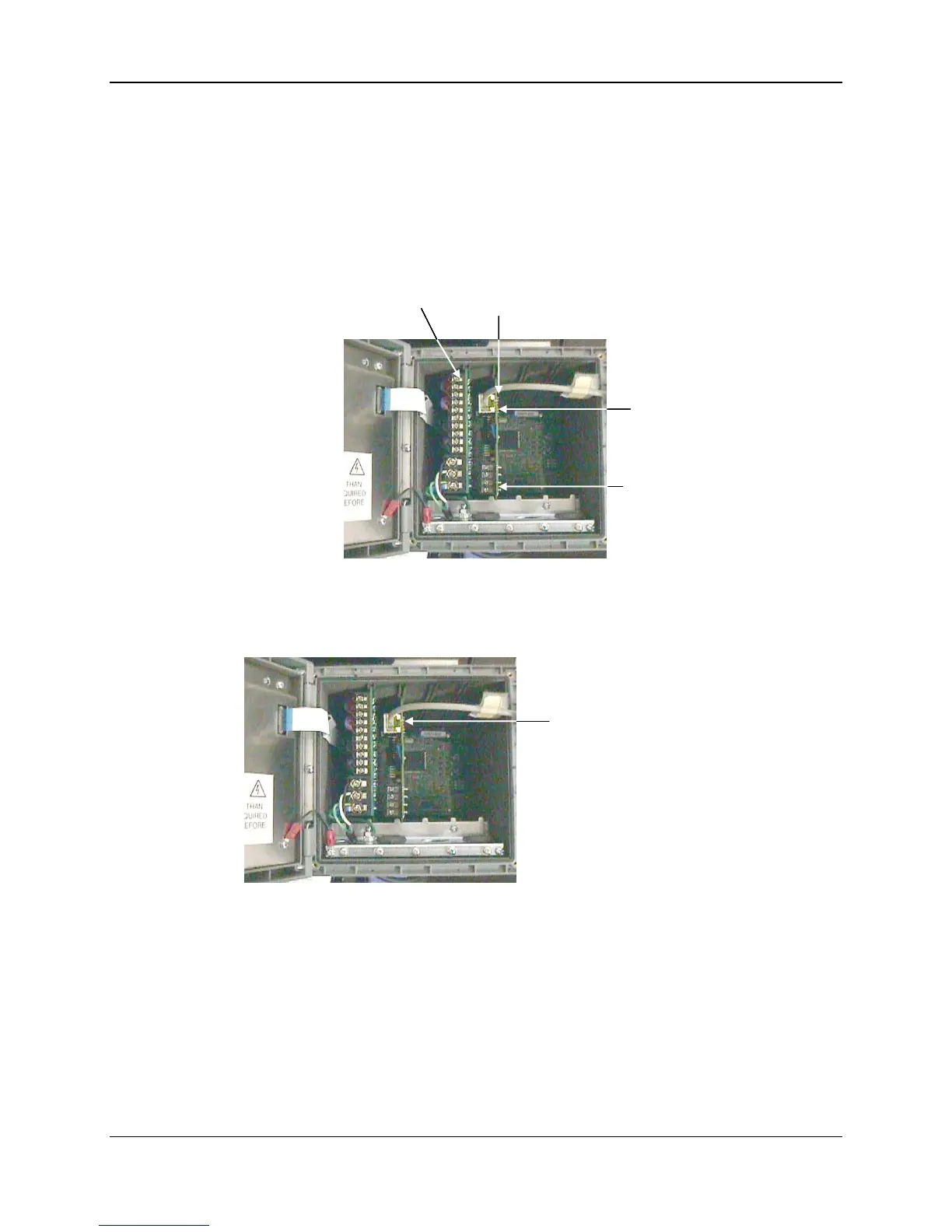
2.2 Ethernet Port Wiring
Ethernet RJ45 ConnectorEthernet RJ45 Connector
Figure 2-2 Ethernet Port Wiring
• Connect terminal 1 of the Communications Card to the chassis ground bar
• Connect an Ethernet cable to the Ethernet card’s RJ45 connector. Cable polarity can be
either Straight-thru or Cross over.
 Loading...