Modbus RTU Serial Communication Port
10 UDA2182 Communications User Guide January 09
4. Modbus RTU Serial Communication Port
4.1 Overview
The Modbus RTU implementation is designed to provide a popular data exchange format connecting the UDA to
both Honeywell and foreign master devices via the optional serial communication port. Modbus RTU allows the
instrument to be a citizen on a data link shared with other devices, which subscribe to the Modicon Modbus
Protocol Reference Guide PI-MBUS-300 Rev. G specification.
The UDA does not emulate any MODICON type device. The Modbus RTU specification is respected in the
physical and data link layers. The message structure of the Modbus RTU function codes is employed and standard
IEEE 32-bit floating point and integer formats are used. Data register mapping is unique to the UDA. Sections 10
and 11 describe the parameter mapping for the UDA.
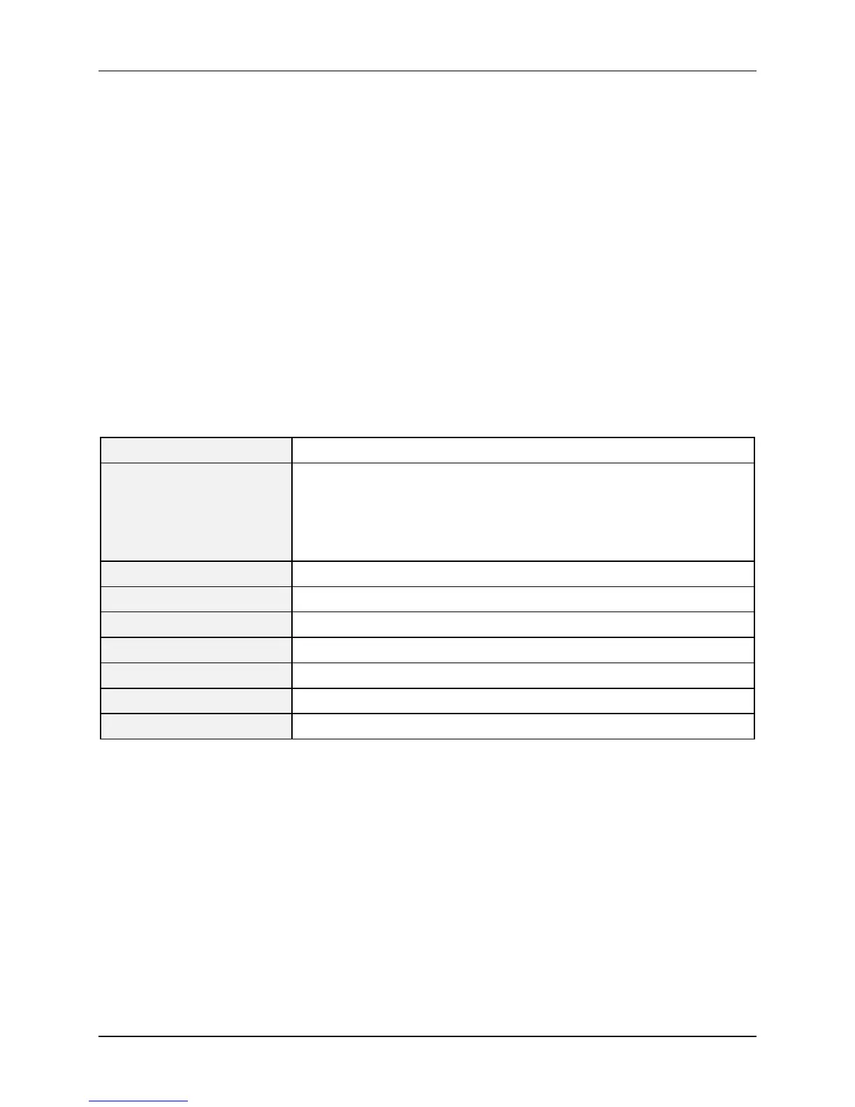
4.2 Modbus RTU Message Format
Table 4-1 Modbus RTU Message Formats
Coding system 8 bit binary
Number of data bits per
character
10 Bits
start bits – 1
data bits – 8
stop bits – 1
Parity None
Bit transfer rate 2400, 4800, 9600, 19200, 38400, 57600, 115200 Selectable
Duplex Half duplex Transceiver or TX/RX
Error checking CRC (cyclic redundancy check)
Polynomial (CRC-16 10100000000001)
Bit transfer order LSB first
End of message Idle line for 3.5 or more characters (>1.82 msec for 19200).
 Loading...