Modbus Double Register Format
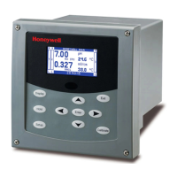
16 UDA2182 Communications User Guide January 09
7. Modbus Double Register Format
7.1 Overview
Data that is 32 bits requires 2 sequential registers (4 bytes) to transfer its data. Data of this type includes
IEEE 32-bit floating point, 32-bit signed integer and 32-bit unsigned integer. The stuffing order of the
bytes into the two registers differs among Modbus hosts. To provide compatibility, the double register
format for the UDA is configurable.
To set the UDA’s double register byte order, go to the Modbus menu in the Setup/Communication menu
and configure Word Swap parameter.
The selections are:
Table 7-1 Modbus Double Register Format Selections
Selection Description Byte order
(See Figure
6-1)
Notes
No Little Endian 3, 4, 1, 2
Yes Big Endian 4, 3, 2, 1 UDA default
NOTE: Word Swapping only applies to Function Codes 3, 4, and 16.
 Loading...
