37
14.INSTALLATION
Only skilled and authorised technicians can install and connect the stove verifying that it functions properly, in compliance with current
regulations and assembling instructions. FONTANA FORNI SRL declines any responsibility for damages to objects and/or persons
caused by improper installation.
15.INSTALLATION REQUIREMENTS
Before installing the stove carefully read the following instructions. More specifically:
- Connect it to the flue for fume exhaustion.
- Connect it to your power supply system.
- Connect it to your heating system.
Connections must be compliant with current regulations; FONTANA FORNI SRL declines any responsibility for damages caused by
improper connections and systems.
16.POSITIONING OF THE STOVE
- Position the stove so that the plug is easily accessible.
- In order to ensure a good functioning and an even distribution of temperature, leave adequate clearance and air for the pellets
to burn, in compliance with installation instructions and national regulations.
- Air will flow through the permanent inlets on the outside walls of the stove.
- Position the stove far from inflammable objects such as wooden furniture, curtains and sofas.
- If the stove is to be supported by a wooden floor, use a floor-protection plate in compliance with national regulations.
- Make sure that the room can provide at least as much air as required by the device normal burning and by room ventilation.
- For your own safety and comfort, please make sure that the room has a suitable air scoop. (UNI10683)
- Do not install the stove in bedrooms or bathrooms.
- The stove cannot be installed in the same room whit another heating device if two independent air pipes are not available.
- Do not position the stove in explosive environments.
- Check that the floor can support the total weight of the stove. For a correct positing of the stove follow the instructions below:
- Put the stove on the floor in a place where it can be easily connected to the flue and to the exhausting and thermal system.
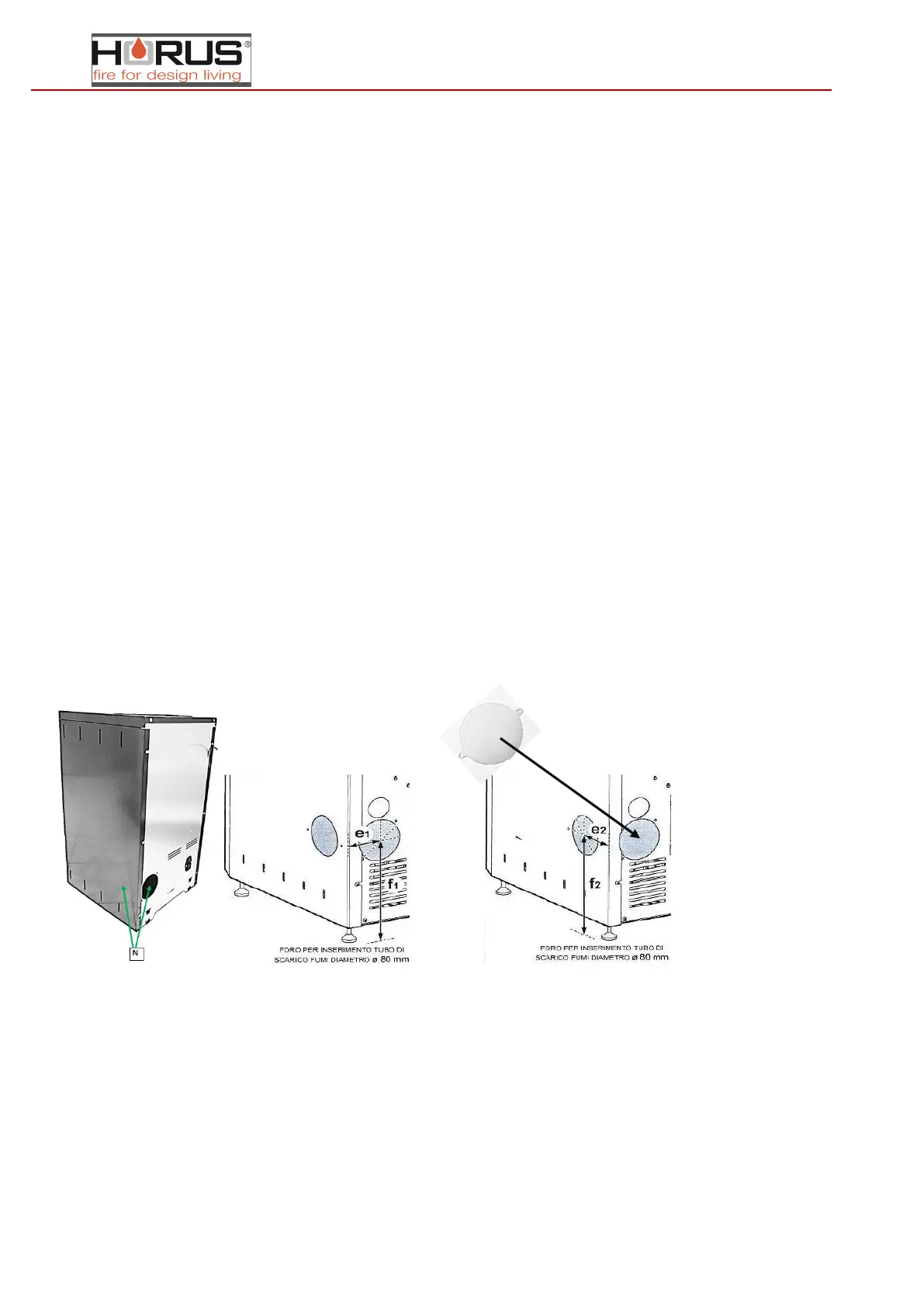
- Connect the flue checking that the fume exhaustion outlet, on the back or on the right side of the stove, is positioned correctly.
(figure 3) FIG. 3 FIG.4
MEASURES FOR REAR FUME EXHAUSTION PIPE CONNECTION (Fig. 4)
f1 = 220 mm e1 =75 mm Diamètre = 80 mm (rear exit.)
f2 = 220 mm e2 =70 mm Diamètre = 95 mm (right exit. Shut attention to the output if not being used)