Assembly
Replacement
Procedures
Overview
In
this
sectioll,
procedures
are
listed for removing
and
installing each assembly. For each assem-
bly, a list
of
Preliminary
Requirements
is listed. To
perform
these
Preliminary
Requirements,
follow
the
steps
shown in each
Preliminary
Item's
replacement
procedure.
Instructions
are
based
on
the
following
orientation
of
the
hardware:
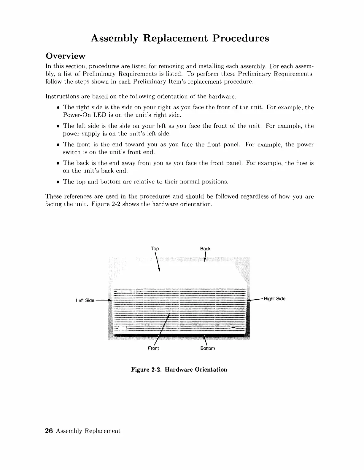
•
The
right side
is
the
side
on
your
right as you face
the
front
of
the
unit.
For example,
the
Power-On
LED
is
on
the
unit's
right side.
•
The
left side is
the
side
on
your
left as you face
the
front
of
the
unit. For example,
the
power
supply
is
on
the
unit's
left side.
•
The
front is
the
end
toward
you as you face
the
front panel. For exalnple,
the
power
switch
is
OIl
the
unit's
front end.
•
The
back is
the
end
away from you as you face
the
front panel. For example,
the
fuse is
on
the
unit's
back end.
•
The
top
and
bottom
are
relative
to
their
normal
positions.
These
references
are
used in
the
procedures
and
should
be
followed regardless
of
how you
are
facing
the
unit.
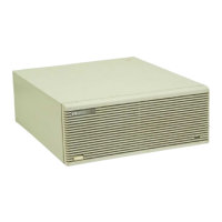
Figure
2-2 shows
the
hardware
orientation.
Back
J
Right Side
I
...
:':
...........................
,
.........
.
Figure 2-2. Hardware Orientation
26
Assembly Replacement
Artisan Technology Group - Quality Instrumentation ... Guaranteed | (888) 88-SOURCE | www.artisantg.com
 Loading...