VI
_
----'-"6+-_-<01
ill
~
....
_'~6
'-----<01
SYSTEIA
DATA
+-
<
t::
...--
~ffi
}
'4/
SYSTEIA
ADDRESS
=-----.:~.r~1
RTC--------+I
AGSYNC
-------.
ACLK---~
GRES----~=====---------------~
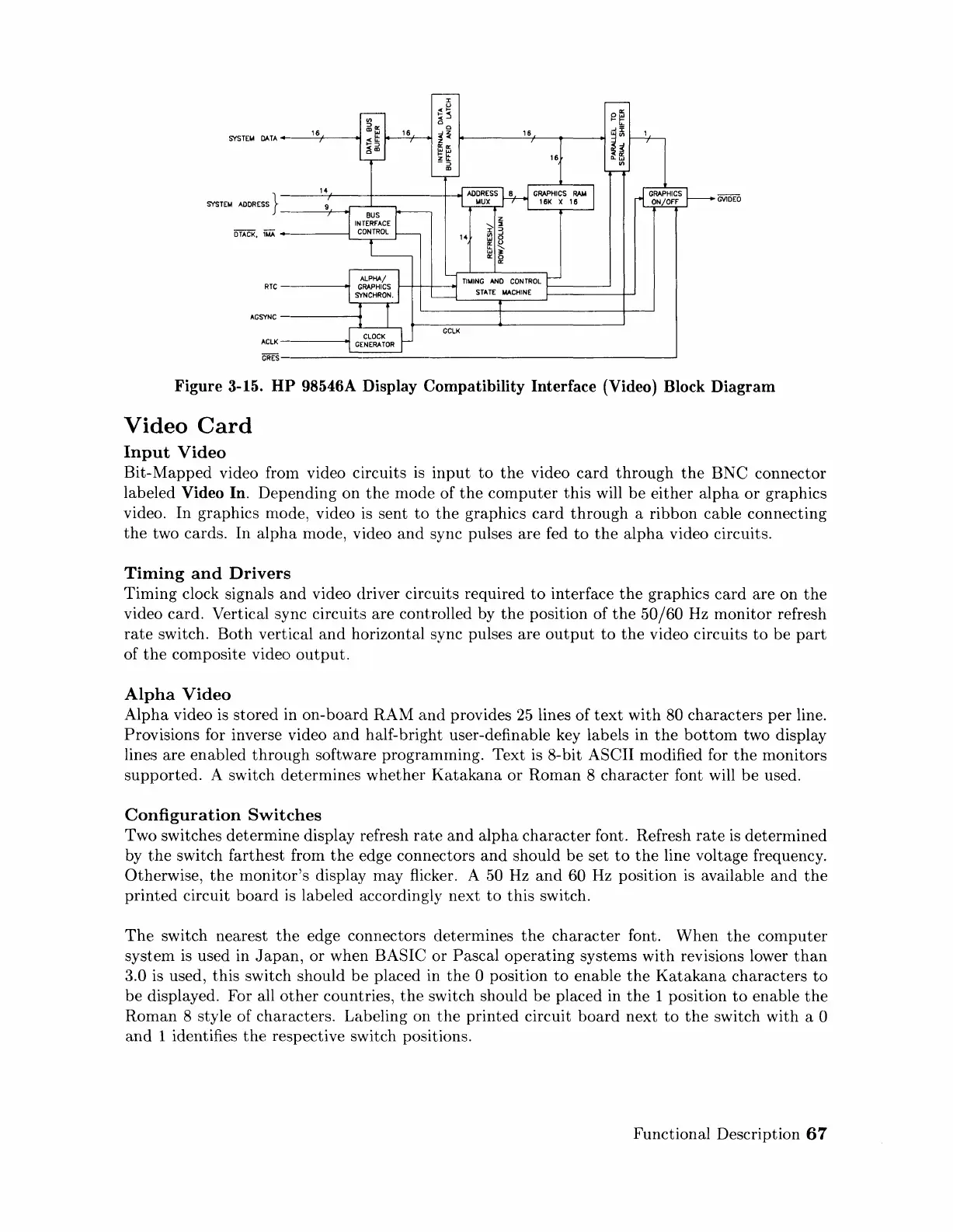
Figure 3-15.
HP
98546A Display Compatibility Interface (Video) Block Diagram
Video
Card
Input
Video
Bit-Mapped
video
frOln
video circuits
is
input
to
the
video
card
through
the
BNC
connector
labeled
Video In. Depending on
the
mode of
the
computer
this
will
be
either
alpha
or
graphics
video.
In
graphics mode, video
is
sent
to
the
graphics
card
through
a ribbon cable connecting
the
two cards.
In
alpha
mode, video
and
sync pulses are fed
to
the
alpha
video circuits.
Tinling
and
Drivers
Timing
clock signals
and
video driver circuits required
to
interface
the
graphics
card
are on
the
video card. Vertical sync circuits are controlled by
the
position of
the
50/60
Hz
monitor
refresh
rate
switch.
Both
vertical
and
horizontal sync pulses are
output
to
the
video circuits
to
be
part
of
the
composite video
output.
Alpha
Video
Alpha
video
is
stored in
on-board
RAM
and
provides
25
lines
of
text
with
80
characters
per
line.
Provisions for inverse video
and
half-bright user-definable key labels in
the
bottom
two display
lines are enabled
through
software programrning. Text is 8-bit ASCII modified for
the
monitors
supported.
A switch determines
whether
Katakana
or
Roman
8
character
font will
be
used.
Configuration
Switches
Two switches determine display refresh
rate
and
alpha
character
font. Refresh
rate
is determined
by
the
switch farthest from
the
edge connectors
and
should be set
to
the
line voltage frequency.
Otherwise,
the
rnonitor's display may flicker. A 50 Hz
and
60 Hz position
is
available
and
the
printed
circuit
board
is
labeled accordingly next
to
this
switch.
The
switch nearest
the
edge connectors determines
the
character
font. When
the
computer
system is used in
Japan,
or
when BASIC
or
Pascal
operating
systems with revisions lower
than
3.0 is used,
this
switch should
be
placed in
the
0 position
to
enable
the
Katakana
characters
to
be
displayed. For all
other
countries,
the
switch should
be
placed in
the
1 position
to
enable
the
Rornan 8 style of characters. Labeling on
the
printed
circuit
board
next
to
the
switch with a 0
and
1 identifies
the
respective switch positions.
Functional Description
67
Artisan Technology Group - Quality Instrumentation ... Guaranteed | (888) 88-SOURCE | www.artisantg.com
 Loading...