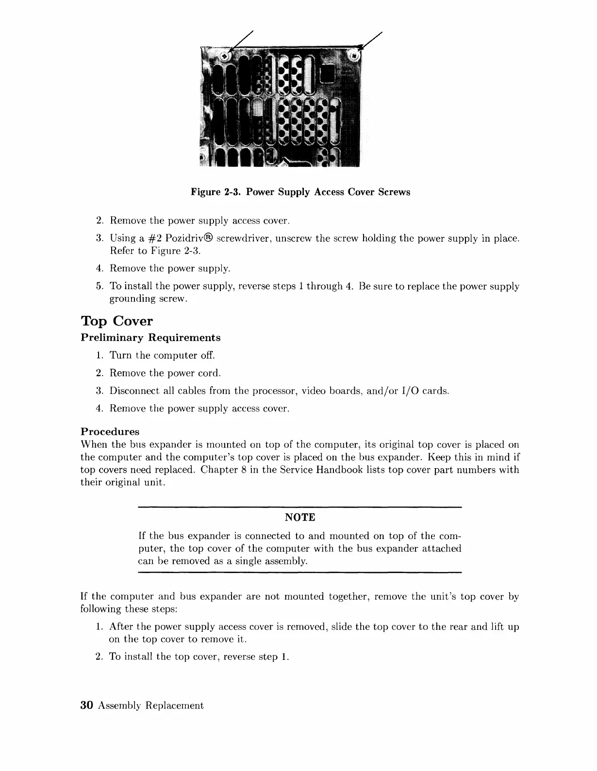
Figure 2-3. Power Supply Access Cover Screws
2.
Remove
the
power supply access cover.
3.
Using a
#2
Pozidriv®
screwdriver, unscrew
the
screw holding
the
power supply in place.
Refer
to
Figure 2-3.
4.
Remove
the
power supply.
5.
To install
the
power supply, reverse steps 1
through
4.
Be sure
to
replace
the
power supply
grounding screw.
Top
Cover
Preliminary
Requirements
1.
Turn
the
computer
off.
2.
Remove
the
power cord.
3.
Disconnect all cables from
the
processor, video boards,
and/or
I/O
cards.
4.
ReIllove
the
power supply access cover.
Procedures
When
the
bus
expander
is
mounted
on
top
of
the
computer, its original
top
cover
is
placed on
the
computer
and
the
computer's
top
cover
is
placed on
the
bus expander. Keep
this
in
mind
if
top
covers need replaced.
Chapter
8 in
the
Service Handbook lists
top
cover
part
numbers with
their
original unit.
NOTE
If
the
bus
expander
is
connected
to
and
mounted
on
top
of
the
com-
puter,
the
top
cover
of
the
computer
with
the
bus
expander
attached
can
be
removed as a single assembly.
If
the
computer
and
bus
expander
are
not
mounted
together, remove
the
unit's
top
cover by
following these steps:
1.
After
the
power supply access cover
is
removed, slide
the
top
cover
to
the
rear
and
lift
up
on
the
top
cover
to
remove it.
2.
To install
the
top
cover, reverse
step
1.
30
Assembly Replacement
Artisan Technology Group - Quality Instrumentation ... Guaranteed | (888) 88-SOURCE | www.artisantg.com
 Loading...