0 0
+4
+2
+3
+1
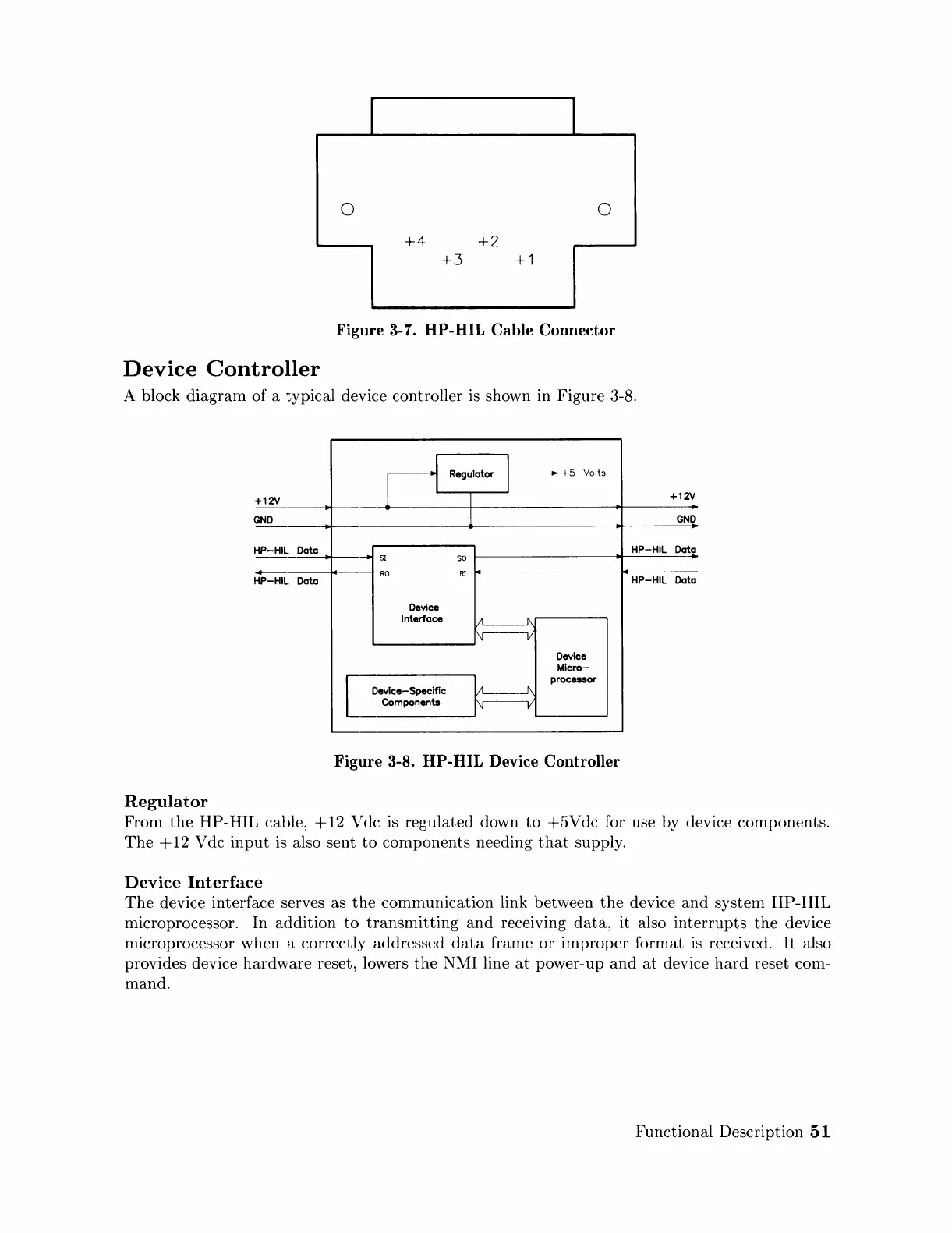
Figure
3-7. HP-HIL
Cable
Connector
Device
Controller
A block
diagram
of a typical device controller
is
shown in Figure 3-8.
Regulator
+12V
GND
HP-HIL
-
HP-HIL
Data
Data
Regulator
I
+5
Volts
L
I
I
+12V
1
GND
HP-HIL
Data
SI
so
RO
Rl
HP-HIL
Data
Device
Interface
Vt------I\
~
Device
Micro-
I
1\
processor
Device-Specific
~
Components
V
Figure
3-8. HP-HIL Device
Controller
From
the
HP-HIL cable,
+12
Vdc
is
regulated down
to
+5Vdc
for use by device components.
The
+
12
V dc
input
is also sent
to
components needing
that
supply.
Device
Interface
The
device interface serves as
the
comnlunication link between
the
device
and
system
HP-HIL
microprocessor. In
addition
to
transmitting
and
receiving
data,
it also
interrupts
the
device
microprocessor when a correctly addressed
data
franle
or
improper
format
is
received.
It
also
provides device
hardware
reset, lowers
the
NMI line
at
power-up
and
at
device
hard
reset com-
mand.
Functional Description
51
Artisan Technology Group - Quality Instrumentation ... Guaranteed | (888) 88-SOURCE | www.artisantg.com
 Loading...