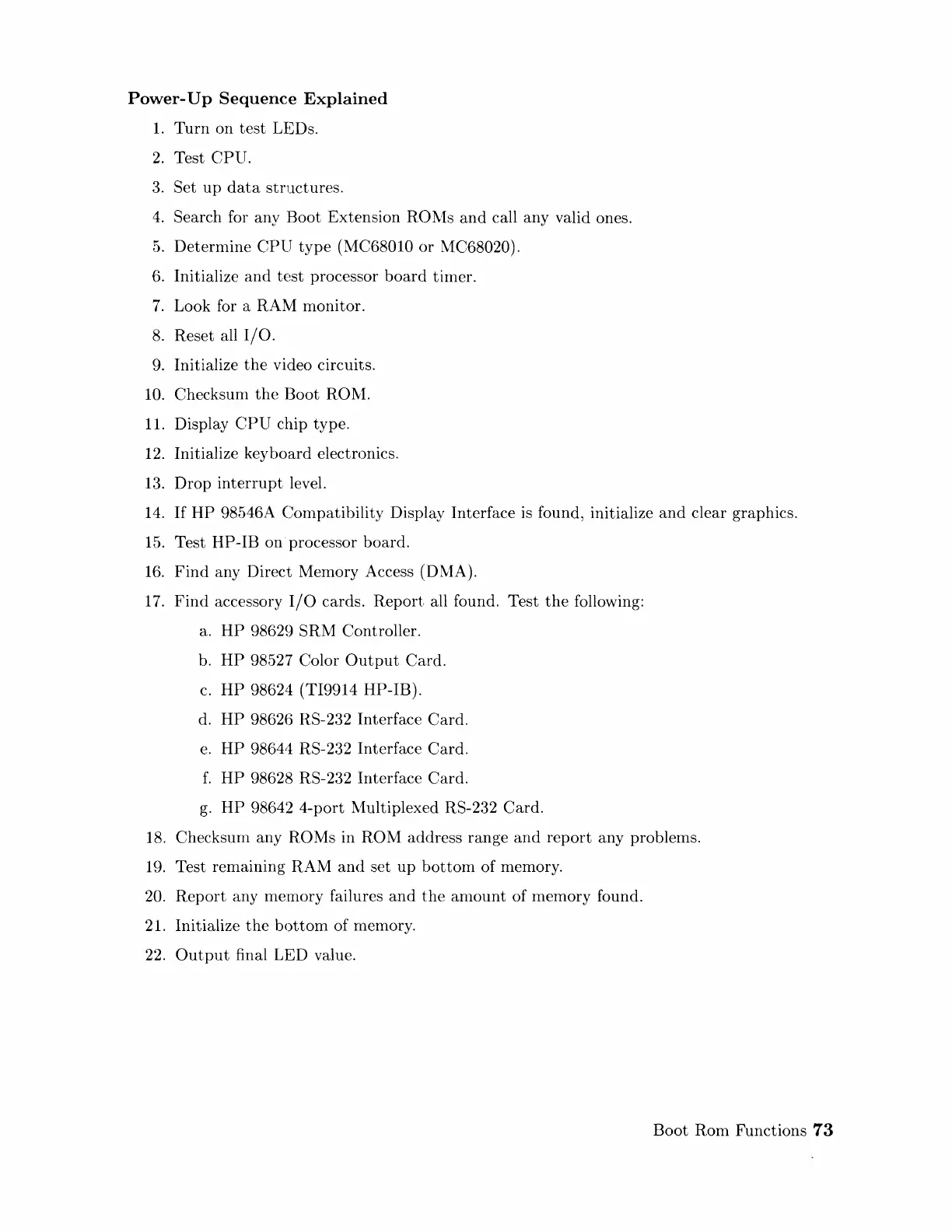
Power-
Up
Sequence
Explained
1.
Turn
on
test
LEDs.
2.
Test
CPU.
3.
Set
up
data
structures.
4.
Search for any Boot Extension R01,1s
and
call any valid ones.
5.
Determine
CPU
type
(MC68010
or
1,1C68020).
6.
Initialize
and
test
processor
board
timer.
7.
Look for a RAM monitor.
8.
Reset all
I/O.
9.
Initialize
the
video circuits.
10. Checksum
the
Boot
RO~1.
11.
Display
CPU
chip type.
12.
Initialize keyboard electronics.
13.
Drop
interrupt
level.
14.
If
HP
98546A Compatibility Display Interface
is
found, initialize
and
clear graphics.
15.
Test HP-IB on
processor
board.
16.
Find
any Direct Memory Access (Dl'vlA).
17.
Find
accessory
I/O
cards.
Report
all found. Test
the
following:
a.
HP
98629 SRM Controller.
b.
HP
98527 Color
Output
Card.
c.
HP
98624 (TI9914 HP-IB).
d.
HP
9862G
RS-232 Interface Card.
e.
HP
98644 RS-232 Interface
Card.
f.
HP
98628 RS-232 Interface Card.
g.
HP
98642
4-port
1,1ultiplexed RS-232
Card.
18.
Checksum any ROMs in ROM address range
and
report
any problems.
19.
Test remaining
RAM
and
set
up
bottom
of memory.
20.
Report
any rnemory failures
and
the
amount
of memory found.
21. Initialize
the
bottom
of memory.
22.
Output
final LED value.
Boot
Rom Functions
73
Artisan Technology Group - Quality Instrumentation ... Guaranteed | (888) 88-SOURCE | www.artisantg.com
 Loading...