Chapter 2 Service
Pre-Troubleshooting Information
2-44 Assembly-Level Service Guide
2
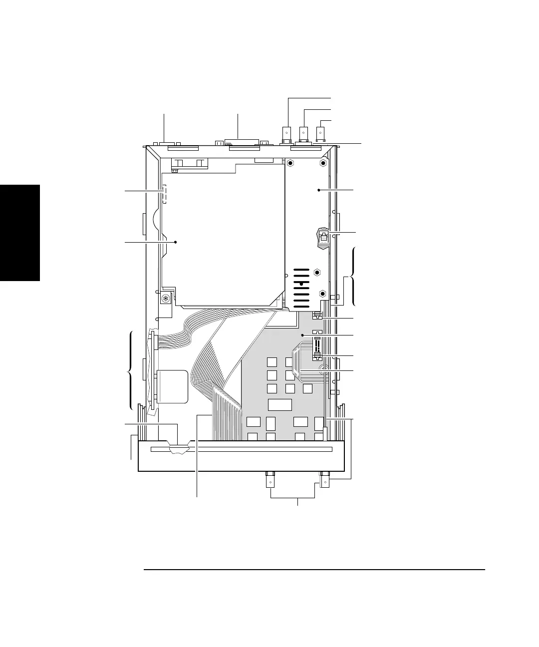
Figure 2-8B. Instrument Top Internal View (Option 002)
A3 Option 030
Channel 3 Assembly for
HP 53131A/132A
OR
A3 Option 015/030
Channel 2 Assembly for
HP 53181A
A3 Option 015/030/050 Channel
Input Board Assembly
Cable (P/O optional channel
input board, Option 015/030 only)
A3 Option 015/030 Channel
Input Board Assembly
Coaxial Cable
(W1)
Input BNC Connectors
(P/O A1 Motherboard Assembly)
Front Bezel
(MP4)
A2 Display Board
Assembly Cable
(P/O Display
Board Assembl
J18 Power Supply
Assembly Connector
RS-232
Connector
HP-IB Connector
Ext Arm Connector
Ref In Connector
10 MHz Out Connector
J9
J6 (Hidden)
J7
4 AC Power Supply
Assembly
A2 Display Board
Assembly
(Hidden)
A5 DC Power Input
Assembly
A1 Motherboard
Assembly
XLR (Male)
Jack (P/O A5)
A6 High Stability
Timebase Assembly