Chapter 3 Replacing Assemblies
To Remove the Front Bezel
3-6 Assembly-Level Service Guide
3
To Remove the Front Bezel
1 Remove the cover.
See the section titled “To Remove the Cover” in this chapter.
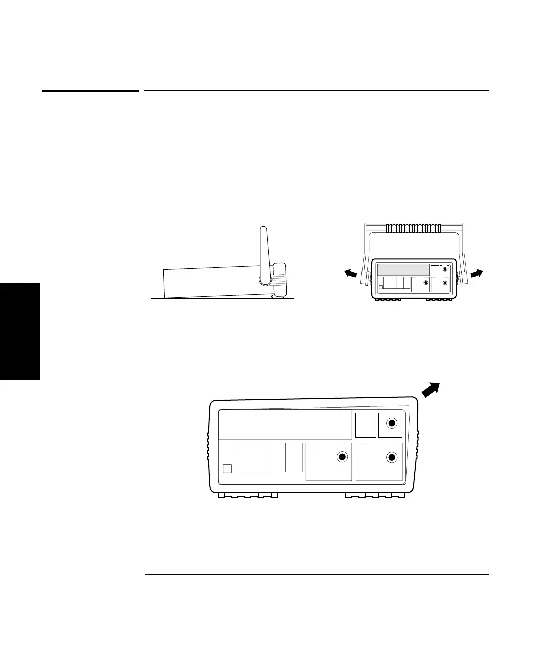
2 Remove the bail handle (MP7) by rotating it to the vertical
position and pull the ends outward as shown in Figure 3-3.
Figure 3-3. Handle Removal
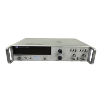
3 Remove the front rubber bumper (part of MP2), stretch a corner
and then slide it off as shown in Figure 3-4.
Figure 3-4. Front Rubber Bumper Removal
4 Disconnect the front bezel flat-ribbon cable (which is actually
A2 Display Board’s cable) from J6 of A1 Motherboard Assembly as
shown in Figure 3-5.