Chapter 1 Performance Tests
Test 1: Trigger Level (HP 53181A Only)
Assembly-Level Service Guide 1-49
1
Procedure
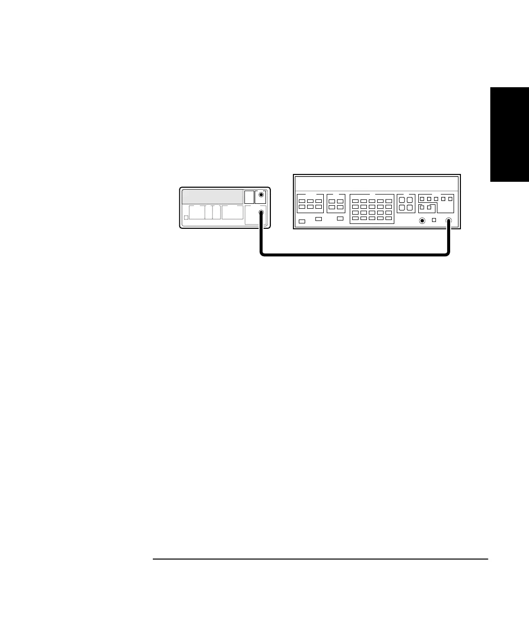
1 Connect the output of the HP 3325B to Channel 1 of the Counter
as shown in Figure 1-11.
Figure 1-11. Trigger Level Test Setup
2 Set the HP 3325B to output a 1 MHz, 80 mVp-p square wave signal.
3 Set the HP 3325B DC OFFSET to
−
60 mV.
4 On the Counter, press Run key.
5 Now, increment the dc offset on the HP 3325B by +1 mV until the
Counter’s
Gate
annunciator flashes and continue incrementing
until the Counter displays approximately 1 MHz.
Observe the offset value on the display of the HP 3325B.
Record the dc offset value__________ mV.
6 Add the upper peak voltage (40 mV) of the 80 mV p-p signal to the
offset value in step 5 (For example,
−
24 mV + 40 mV = 16 mv).
This is the upper hysteresis level.
Record the upper hysteresis level__________ mV.
HP 53181A
Counter
Channel 1
HP 3325B
Synthesizer
Output