Chapter 3 Replacing Assemblies
To Remove the A2 Display Board, Keypads, and Window
Assembly-Level Service Guide 3-11
3
To Remove the A2 Display Board, Keypads,
and Window
1 Remove the cover.
See the section titled “To Remove the Cover” in this chapter.
2 Remove the front bezel.
See the section titled “To Remove the Front Bezel” in this chapter.
3 Note that A2 Display Board Assembly, shown in Figure 3-7, is held
in place by five tabs (two on top and three on bottom) which are
part of the front bezel.
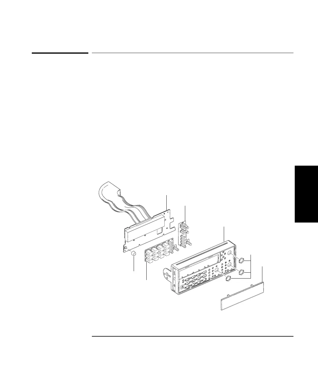
Figure 3-7. A2 Display Board, Keypad, and Window Removal
A2 Display Board Assembly
P/O Rubber Keypads (MP6)
Front Bezel (MP4)
Window (MP5)
Cap
BNC Nuts (H3)
P/O Rubber Keypads (MP6)
(Shown with
Optional Channel 3)