Chapter 1 Performance Tests
HP 53131A/132A/181A Operational Verification
Assembly-Level Service Guide 1-11
1
Procedure
1 Set the Pulse Generator to the following:
PERIOD: 20
µ
s
WIDTH: 5
µ
s
High: 3.00 V Low : 0.8 V
Trailing/Leading : 1.0 ns
Input Mode: TRIG
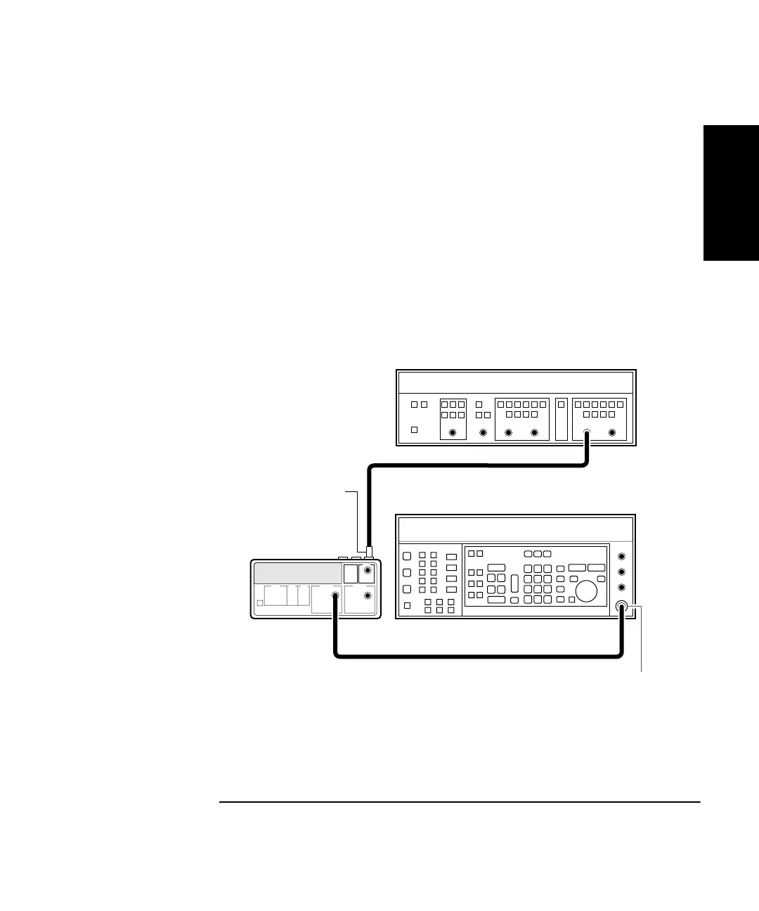
2 Connect the equipment as shown in Figure 1-3.
Figure 1-3. External Arm Test Setup (HP 53131A/132A Only)
HP 8130A
Pulse Generator
Counter
HP 8663A
Synthesized Signal Generator
N-to-BNC
Connector
Output
Channel 1
50Ω
Feedthrough
Ext Arm
(rear panel)
Output