Chapter 7 HP 53131A/132A Specifications
Measurement Definitions
7-12 Assembly-Level Service Guide
7
Measurement Definitions
Definitions of Systematic Uncertainty Terms
• Trigger Error
External source and input amplifier noise may advance or delay the trigger points that define the beginning and end of a measurement.
The resulting timing uncertainty is a function of the slew rate of the signal and the amplitude of spurious noise spikes (relative to the input
hysteresis band).
The (rms) trigger error associated with a single trigger point is:
where
E
input
= RMS noise of the input amplifier: 1 mVrms (350 µVrms typical). Note that the internal measurement algorithms significantly
reduce the contribution of this term.
E
signal
= RMS noise of the input signal over a 225 MHz bandwidth (100 kHz bandwidth when the low-pass filter is enabled). Note that
the filter may substantially degrade the signal’s slew rate at the input of the trigger comparator.
For two-trigger-point measurements (e.g. Rise Time, Pulse Width), the Trigger Errors will be referred to independently as Start Trigger Error
and Stop Trigger Error.
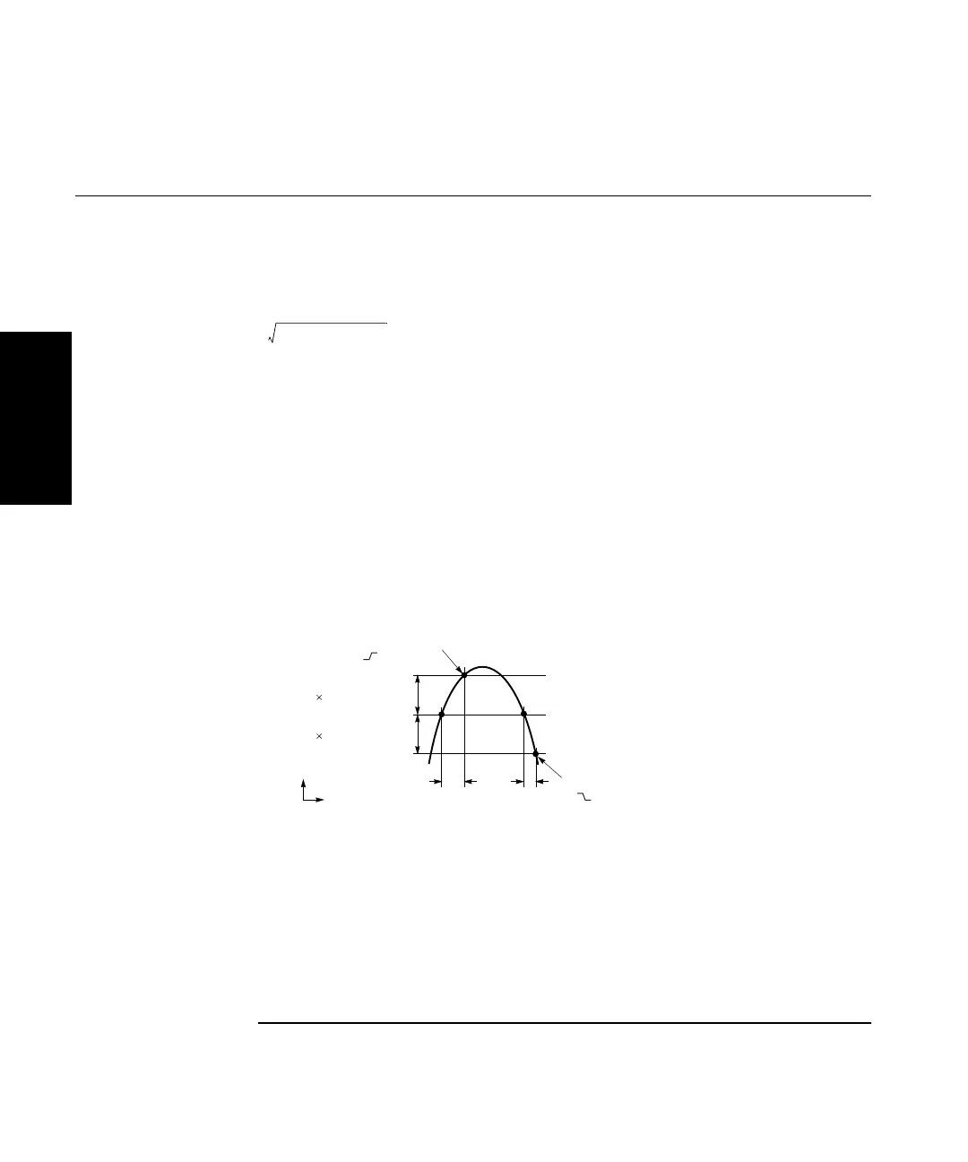
• Trigger Level Timing Error
Trigger level timing error results from a deviation of the actual trigger level from the specified (indicated) level. The magnitude of the
measurement timing error depends on several factors, primarily: resolution and accuracy of the trigger level circuit, fidelity of the input
amplifier, slew rate of the input signal at the trigger point, and width of the input hysteresis band (see illustration).
Trigger level timing error is associated with Time Interval, Pulse Width, Rise Time, Fall Time, Phase, and Duty Cycle measurements.
The following equations define the general interpretation of its component error terms for a measurement. These should be summed
together to obtain the overall Trigger Level Timing Error.
Trigger Error
E
input
()
2
E
signal
()
2
+
Input Signal Slew Rate at Trigger Point
-------------------------------------------------------------------------------------------------------
(in seconds)
=
Upper Hystersis Limit
Trigger Level Setting
Lower Hystersis Limit
Actual Trigger Point:
Slope
Trigger Level Timing Errors
0.5 Hysteresis Band
0.5 Hysteresis Band
Amplitude
Time
Actual Trigger Point:
Slope
Input Hysteresis:
0.5 Hysteresis Band
×
Input Signal Slew Rate at Start Trigger Point
---------------------------------------------------------------------------------------------------------------------
0.5 Hysteresis Band
×
Input Signal Slew Rate at Stop Trigger Point
---------------------------------------------------------------------------------------------------------------------
–
Trigger Level Setting:
15 mV 1% Start Trigger Level Setting
×()±
Input Signal Slew Rate at Start Trigger Point
---------------------------------------------------------------------------------------------------------------------
15 mV 1% Stop Trigger Level Setting
×()±
Input Signal Slew Rate at Stop Trigger Point
---------------------------------------------------------------------------------------------------------------------
±±