Chapter 3 Replacing Assemblies
To Remove A1 Motherboard Assembly
3-10 Assembly-Level Service Guide
3
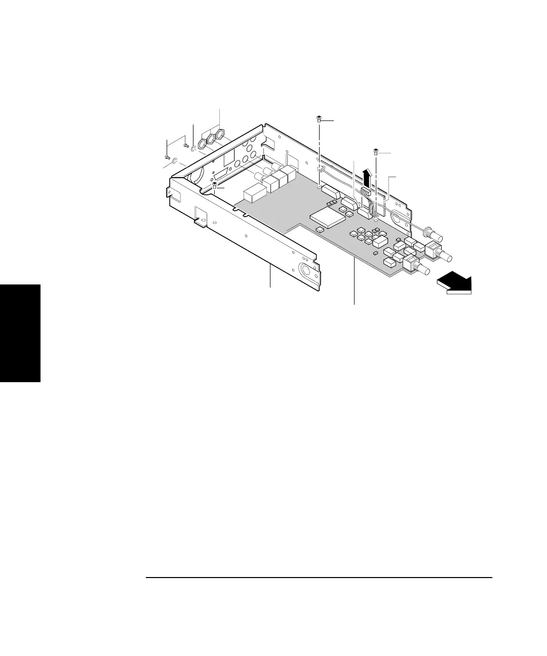
Figure 3-6. A1 Motherboard Assembly Removal
8 Remove the BNC nuts (H3), shown in Figure 3-6, from the rear of
the chassis using the 14-mm deep-socket spin tight (Opt 015/030
only). Remove knurled nut for Option 050.
9 Remove the three screws (H1) in A1 Motherboard Assembly as
shown in Figure 3-6.
10 Finally, slide the motherboard assembly forward.
H4
H1
H1
H1
H5
H3
A1 Motherboard
Assembly
H5
MP1
A3 1.5/3.0 GHz
Channel Assembly
(Option 015/030)
J7