Chapter 3 Replacing Assemblies
To Remove the Front Bezel
Assembly-Level Service Guide 3-7
3
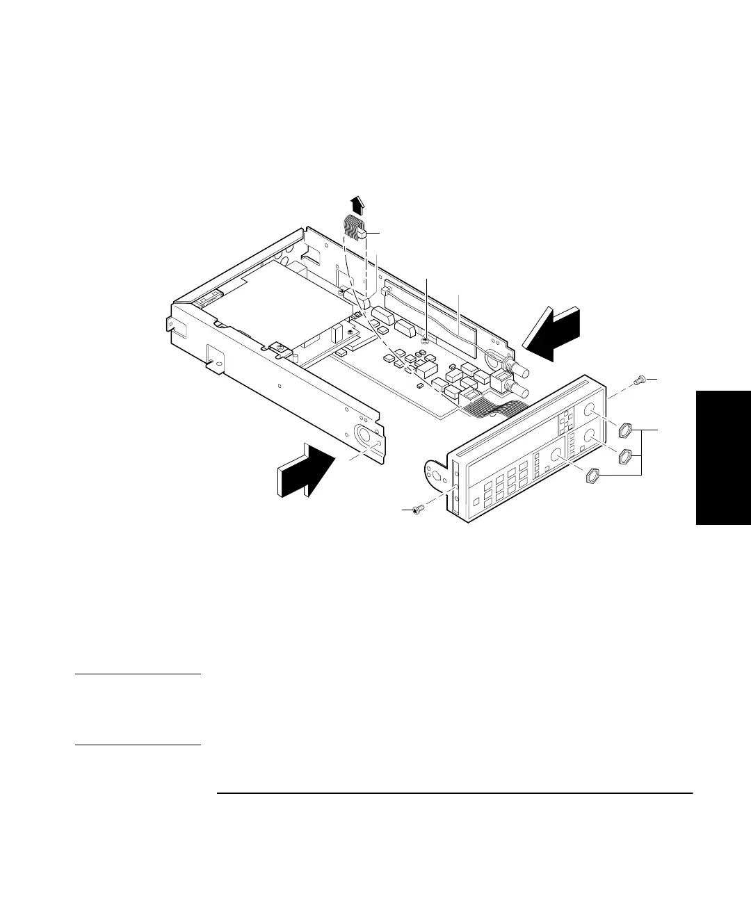
5 Remove the BNC nuts (H3), shown in Figure 3-5, from the front
panel using the 14-mm deep-socket spin tight.
Figure 3-5. Front Bezel Removal
6 For Counters with the optional 1.5 GHz or 3.0 GHz channel
(Option 015 or 030), pull cable W1 out of the front bezel as shown
in Figure 3-5. For the optional 5.0 or 12.4 GHz channel, remove
knurled nut.
CAUTION When reassembling A3 (Option 015/030) Assembly, ensure that cable W1
is not placed or folded on top of the input circuits of A1 Motherboard
Assembly or is tucked behind A3 as the Counter may start reading or
measuring noise.
H3
H1
H1
W1
J6
P/O A2 Display Board Cable
H1