Chapter 4 Retrofitting Options
To Retrofit A5 DC Power Input Assembly (Option 002)
4-6 Assembly-Level Service Guide
4
4 Insert and tighten the two hex screws (H4) and the lock washers
(H5) onto the HP-IB connector that protrudes from the rear of the
chassis using the 7-mm spin tight.
5 Now, re-install the front bezel by performing the front bezel
removal procedure, in Chapter 3 of this guide, in reverse. Be sure
to insert A2 Display Board’s cable into connector J6 on
A1 Motherboard Assembly.
6 Tighten the three H1 screws, shown in Figure 4-1A, to secure the
motherboard to the chassis.
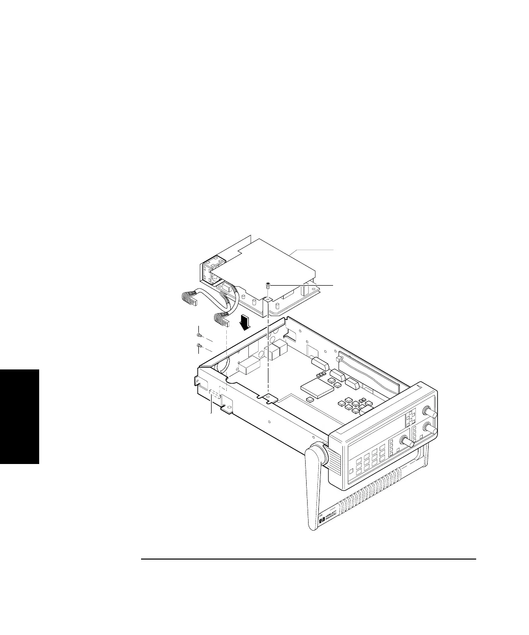
Figure 4-1B. DC Power Input Assembly Retrofitting
H2
H2
H1
J18
A4 AC Power Supply
Assembly