16
The general sequence
to
read
the
measured'magnitude
or
phase value
at
any
point
on
the
trace
is
as
follows:
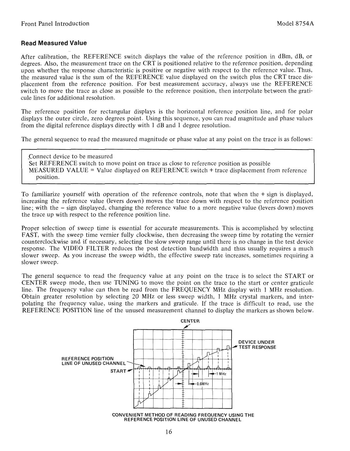
CONVENIENT METHOD OF READING FREQUENCY USING THE
REFERENCE POSITION
LINE
OF UNUSED
CHANNEL
Model
8754A
DEVICE UNDER
~TEST
RESPONSE
,....
.fL
X
/t"'
...
I
n
I
I
--...
~
JV
vt"'
I
I
I
~
,r".
,r.'!
.r.1
.m
.rh.
},
.f.,
I
.m
.."
,
I
I
,
lY~
H
~
I
I
I
I
~1
MHz
I I .L
I
I
I
)V
~
.....
It-
O.6MHz
I
I
rv
,
]v
V
I
I
yV
Front
Panel
Introduction
REFERENCE POSITION
LINE OF UNUSED
CHANNEL
START
Proper selection
of
sweep time
is
essential for accurate measurements. This
is
accomplished
by
selecting
FAST, with
the
sweep time vernier fully clockwise,
then
decreasing
the
sweep time
by
rotating
the
vernier
counterclockwise and
if
necessary, selecting
the
slow sweep range until there
is
no change in
the
test device
response. The VIDEO
FILTER
reduces
the
post detection
bandwidth
and thus usually requires a
much
slower sweep.
As
you
increase
the
sweep width,
the
effective sweep rate increases, sometimes requiring a
slower sweep.
The general sequence
to
read
the
frequency value
at
any
point
on
the
trace
is
to
select
the
START
or
CENTER sweep mode,
then
use TUNING
to
move
the
point
on
the
trace
to
the
start
or
center
graticule
line. The frequency value can
then
be read from
the
FREQUENCY
MHz
display with I MHz resolution.
Obtain greater resolution
by
selecting 20 MHz
or
less sweep width, 1
MHz
crystal markers,
and
inter-
polating
the
frequency value, using
the
markers and graticule.
If
the
trace
is
difficult
to
read, use
the
REFERENCE POSITION line
of
the
unused measurement channel
to
display
the
markers
as
shown below.
CENTER
/'
Connect device
to
be measured
Set REFERENCE switch
to
move
point
on
trace
as
close
to
reference position
as
possible
MEASURED VALUE
= Value displayed
on
REFERENCE switch + trace displacement from reference
position.
To familiarize yourself with operation
of
the
reference controls,
note
that
when
the
+ sign
is
displayed,
increasing
the
reference value (levers down) moves
the
trace down with respect
to
the
reference position
line; with
the
- sign displayed, changing
the
reference value
to
a more negative value (levers down) moves
the trace
up
with respect
to
the
reference position line.
The reference position for rectangular displays
is
the
horizontal reference position line, and for polar
displays
the
outer
circle, zero degrees point. Using this sequence,
you
can read magnitude and phase values
from
the
digital reference displays directly with I dB
and
I degree resolution.
Read Measured Value
After calibration,
the
REFERENCE switch displays
the
value
of
the
reference position in dBm, dB,
or
degrees. Also,
the
measurement trace
on
the
CRT
is
positioned relative
to
the
reference position, depending
upon
whether
the response characteristic
is
positive
or
negative with respect
to
the
reference value. Thus,
the measured value
is
the
sum
of
the
REFERENCE value displayed
on
the
switch plus
the
CRT trace dis-
placement from
the
reference position.
For
best measurement accuracy, always use
the
REFERENCE
switch
to
move
the
trace as close as possible
to
the
reference position,
then
interpolate between
the
grati-
cule lines for additional resolution.
Artisan Technology Group - Quality Instrumentation ... Guaranteed | (888) 88-SOURCE | www.artisantg.com