Model
8754A
Reflection Measurements
REFLECTION MEASUREMENTS
The
8754A displays
Return
Loss
(A/R)
using Channel 1
or
displays reflection coefficient
(POLAR
A/R)
using
Channel
1 for
magnitude
ratio
and
Channel
2 for phase angle.
The
calibration
standard
for reflection
measurements
is
a
short
circuit
at
the
point
at
which the test device will be connected. Complete reflection
calibration sets
the
magnitude
ratio
between the incident
and
reflected signal
to
0 dB
and
the phase angle
to
± 180
0
,
the
value for a
short
circuit.
The
following
paragraphs
describe calibration
and
measurement in
separate sequences,
but
calibration for
Return
Loss also calibrates
POLAR
A/R
magnitude
ratio.
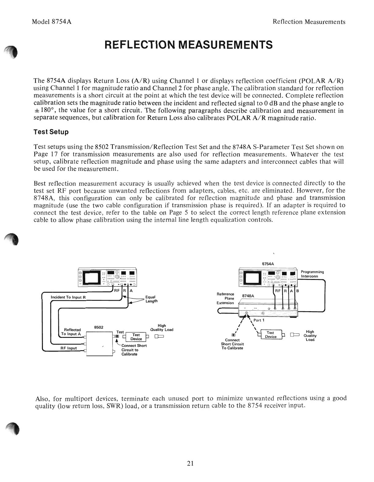
Test Setup
Test setups using the 8502
Transmission/Reflection
Test Set
and
the 8748A
S-Parameter
Test Set shown
on
Page
17 for transmission measurements
are
also used for reflection measurements. Whatever the test
setup, calibrate reflection magnitude
and
phase using the same adapters
and
interconnect cables
that
will
be used for the measurement.
Best reflection measurement accuracy
is
usually achieved when the test device
is
connected directly
to
the
test set
RF
port
because
unwanted
reflections from adapters, cables, etc. are eliminated. However, for
the
8748A, this configuration can only be calibrated for reflection magnitude and phase and transmission
magnitude (use
the
two cable configuration
if
transmission phase
is
required).
If
an adapter
is
required
to
connect the test device, refer
to
the table on Page 5
J
to
select the correct length reference plane extension
cable
to
allow phase calibration ·using the
intemalline
length equalization controls.
8754A
High
Quality
Load
\
Port
1
\
\
~
Test
Device
I
I
I
,
[IJ
Connect
Short
Circuit
To
Calibrate
rD::~··
Programming
@
00~
~~~o:@
~~~
0
;~o~
Interconn
@
000000000000
0000
co
00Ci
-G)eG
eG
lRF
R
A B
Reference
8748A
Plane
Extension
/
II
o·
Do
@
(D
b
<D
D
(
..."
-
Equal
Length
High
Test
Quality Load
~
9
D~~~~
PD=J
Connect
Short
Circuit
to
Calibrate
8502
Reflected
To
Input
A
RF
Input
Incident
To
Input
R
~II
II
:0:
I~~I~
J~
@
00
c
00000
0000
0000
co
Doe
eo
,..-
----'
RF R A
Also, for
multiport
devices, terminate each unused
port
to
mInImIze
unwanted
reflections using a good
quality (low return loss, SWR) load,
or
a transmission
return
cable
to
the
8754 receiver input.
21
Artisan Technology Group - Quality Instrumentation ... Guaranteed | (888) 88-SOURCE | www.artisantg.com