Model 8754A
Storage Normalizer
Matching the 8750A to the 8754A
Alignment
may
be required when the 8750A
is
first connected
to
the 8754A.
Perform
the following align-
ment sequence when the trace differs significantly (greater
than
±
1/2
minor division) between the bypass
and
input
modes
and
the difference
cannot
be corrected using the 8750A front panel horizontal
and
ver-
tical adjustments.
A5
A5
08750-600368754A
INTERFACE
BOARD
o
00000
0
~
8
~
g
0000
~.
o g
~O
SWITCHES SET
AT
EXT.
08760-60005 NETWORK
ANALYZER
INTERFACE
BOARD
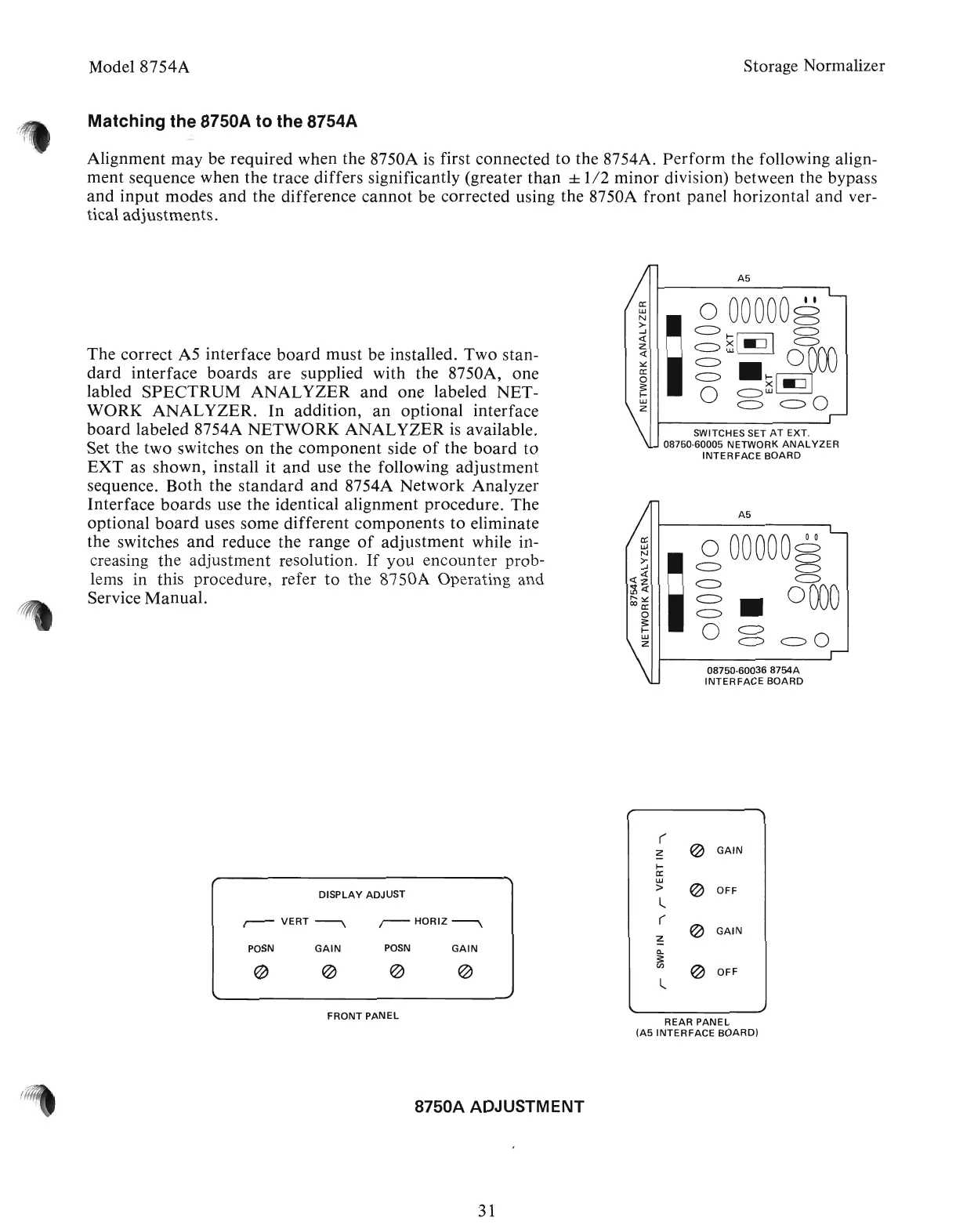
The correct A5 interface
board
must be installed. Two stan-
dard
interface
boards
are
supplied with the 8750A, one
labled
SPECTRUM
ANALYZER
and
one labeled NET-
WORK
ANALYZER.
In
addition,
an
optional interface
board
labeled 8754A
NETWORK
ANALYZER
is
available.
Set the two switches
on
the
component
side
of
the
board
to
EXT
as shown, install it
and
use the following
adjustment
sequence.
Both
the
standard
and
8754A Network Analyzer
Interface
boards
use the identical alignment procedure. The
optional
board
uses some different components
to
eliminate
the switches
and
reduce the range
of
adjustment
while in-
creasing
the
adjustment resolution.
If
you encounter prob-
lems in this procedure, refer
to
the 8750A Operating and
Service
Manual.
(
~
~
GAIN
~
a:
w
~
DISPLAY
ADJUST
>
OFF
l
r-VERT~
,--HORIZ~
(
~
GAIN
~
POSN
GAIN
POSN
GAIN
Q.
3:
@
~
~
~
en
@
OFF
l
FRONT
PANEL
REAR
PANEL
(A5
INTERFACE
BOARD)
8750A ADJUSTMENT
31
Artisan Technology Group - Quality Instrumentation ... Guaranteed | (888) 88-SOURCE | www.artisantg.com