Model
8754A
Transmission Measurements
Insertion Phase
For
a valid insertion phase calibration
the
electrical length
of
the
reference and transmitted signal paths
must be equal with a
"through"
connection. Refer
to
the
phase calibration discussion, page 15. Measure
insertion phase
as
follows:
CALIBRATION
Connect a
"through."
Set CRT display (reference position line
to
center), frequency sweep, and signal levels.
Channel 2, Select:
PHASE
B/R.
Set REFERENCE switch
to
± 00.
Adjust
BIR
LENGTH and
OFFSET
for constant 0
0
over sweep.
MEASUREMENT
Connect test device.
Set REFERENCE switch
to
move
point
of
interest
on
trace
to
reference position line.
Read phase angle from REFERENCE switch setting.
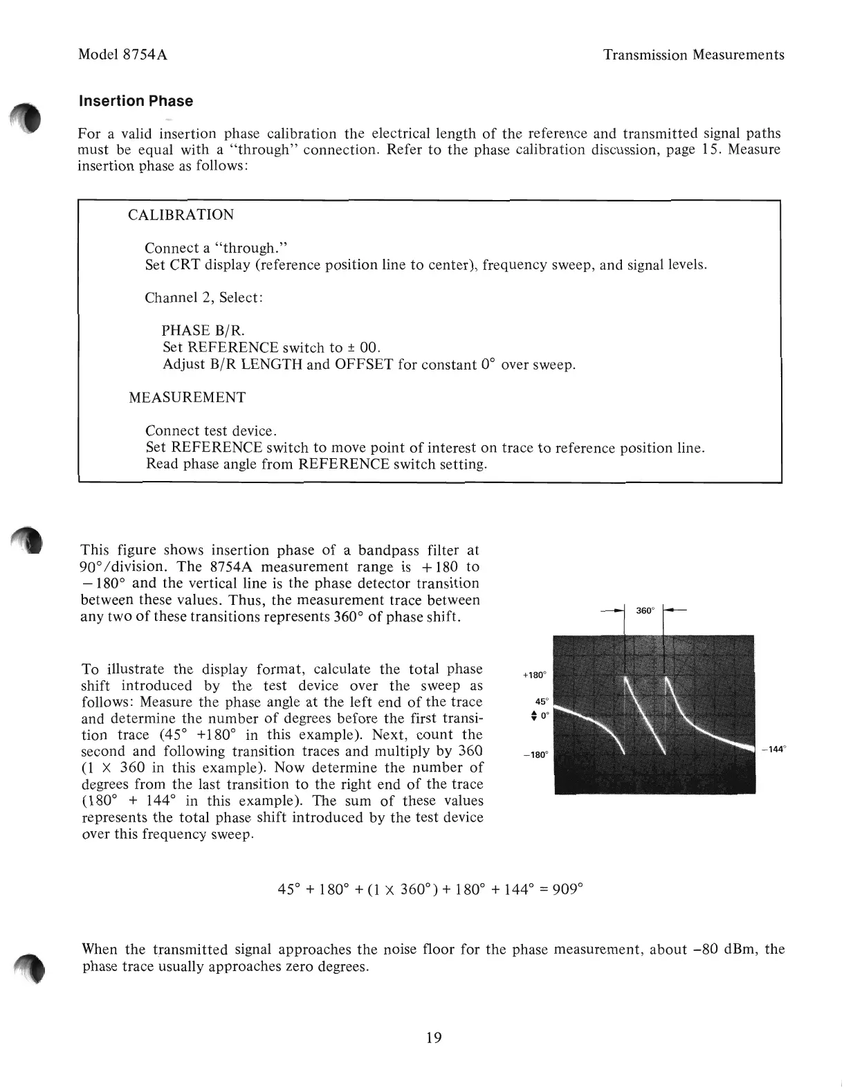
This figure shows insertion phase
of
a
bandpass
filter
at
90
0
/division.
The
8754A measurement range
is
+ 180
to
- 180
0
and
the vertical line
is
the phase detector transition
between these values.
Thus,
the measurement trace between
any two
of
these transitions represents 360
0
of
phase shift.
To illustrate
the
display format, calculate
the
total
phase
shift introduced
by
the
test device over
the
sweep as
follows: Measure
the
phase angle
at
the
left end
of
the
trace
and determine
the
number
of
degrees before
the
first transi-
tion trace (45
0
+180
0
in this example). Next,
count
the
second and following transition traces and multiply
by
360
(1
X
360
in this example). Now determine
the
number
of
degrees from
the
last transition
to
the
right end
of
the
trace
(180
0
+ 144
0
in this example). The sum
of
these values
represents
the
total
phase shift
introduced
by
the
test device
over this frequency sweep.
When
the
transmitted signal approaches
the
noise floor for
the
phase measurement,
about
-80
dBm,
the
phase trace usually approaches zero degrees.
19
Artisan Technology Group - Quality Instrumentation ... Guaranteed | (888) 88-SOURCE | www.artisantg.com