Model
8754A
Storage Normalizer
_USING
THE
8750A STORAGE-NORMALIZER
The
8750A
provides
independent
storage and norm-
alization for each
of
the
two
8754A
measurement
channels. In general,
8750A
operating modes are
selected
by
pressing CH1
or
CH2
to
choose
the
active display channel,
then
pressing one
of
the
Display
or
Reference
buttons
to
choose
the
active
channel operating mode. The active display channel
is
identified
by
the
lighted
indicator
in
the
center
of
the
CHI
or
CH2
button,
and
the
mode
is identified
by
a lighted
indicator
above one
of
the
Display
or
Reference
buttons
.
.!
All 8754A setup,
calibration,
and
measurement
sequences described in this
manual
can
be accomplished
using
the
8750A except
POLAR
A/R
measurements.
Pressing BYPASS removes the 8750A
from
the
display circuits
and
returns
the
CRT
to
standard
analog
operation.
(The 8750A
automatically
switches
to
bypass
when
POLAR
A/R
is
selected.) Pressing
any
Display
button
activates the 8750A
and
both
measurement
channels
are
displayed
according
to
the
last Display
Mode
selection.
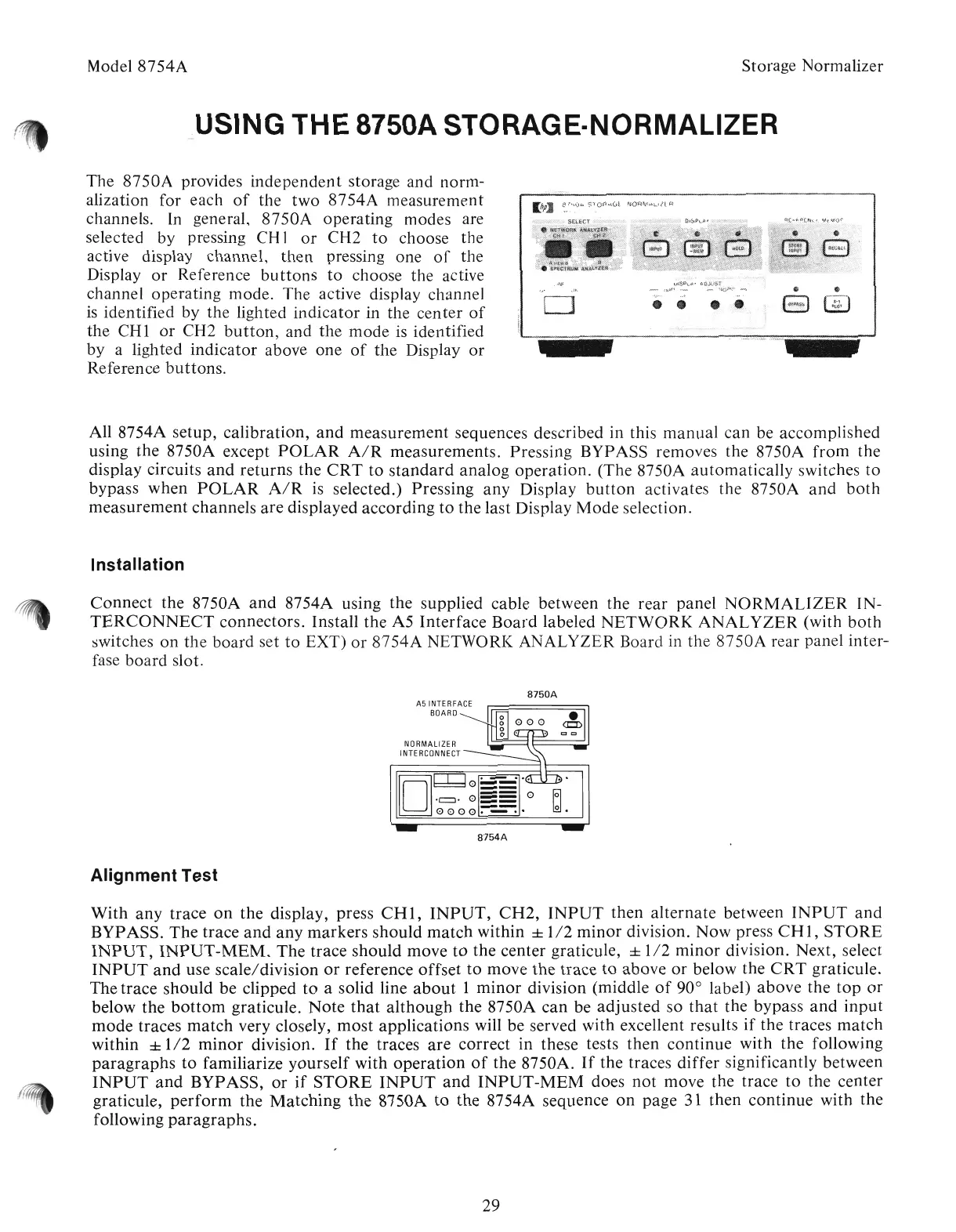
Installation
Connect
the 8750A
and
8754A using
the
supplied cable between the
rear
panel
NORMALIZER
IN-
TERCONNECT
connectors.
Install
the
A5
Interface
Board
labeled
NETWORK
ANALYZER
(with
both
switches
on
the
board
set
to
EXT)
or
8754A
NETWORI( ANALYZER Board in
the
8750A
rear panel inter-
fase
board
slot.
8750A
A5
INTERFACE
BOARD
NORMALIZER
INTERCONNECT
[OJ
r-r-l
~
...
~0==
.c:::l.
0
==
0
o
0000:-:::-:'
8754A
Alignment Test
With
any
trace
on
the
display, press
CHI,
INPUT,
CH2,
INPUT
then
alternate
between
INPUT
and
BYPASS.
The
trace
and
any
markers
should
match
within ±
1/2
minor
division.
Now
press
CHI,
STORE
INPUT,
INPUT-MEM.
The
trace
should
move
to
the
center graticule, ±
1/2
minor
division. Next, select
INPUT
and
use
scale/division
or
reference
offset
to
move
the
trace
to
above
or
below the
CRT
graticule.
The
trace
should
be
clipped
to
a solid line
about
1
minor
division (middle
of
90° label)
above
the
top
or
below
the
bottom
graticule.
Note
that
although
the
8750A
can
be
adjusted
so
that
the bypass
and
input
mode
traces
match
very closely,
most
applications will be served with excellent results
if
the traces
match
within ±
1/2
minor
division.
If
the traces
are
correct
in these tests
then
continue
with
the
following
paragraphs
to
familiarize
yourself
with
operation
of
the 8750A.
If
the traces
differ
significantly between
INPUT
and
BYPASS,
or
if
STORE
INPUT
and
INPUT-MEM
does
not
move the trace
to
the center
graticule,
perform
the
Matching
the
8750A
to
the
8754A sequence
on
page 31
then
continue
with
the
following
paragraphs.
29
Artisan Technology Group - Quality Instrumentation ... Guaranteed | (888) 88-SOURCE | www.artisantg.com