. Model
8754A
Reflection Coefficient
Reflection coefficient is a
complex
value consisting
of
a
linear
magnitude
ratio
and
a
phase
angle.
The
notation
used
is
p L
f/J
where
p
equals
the
linear
magnitude
ratio
between
the
incident
and
the
reflected signal
and
L
f/J
represents
the
phase
angle
between
the
incident
and
reflected signal.
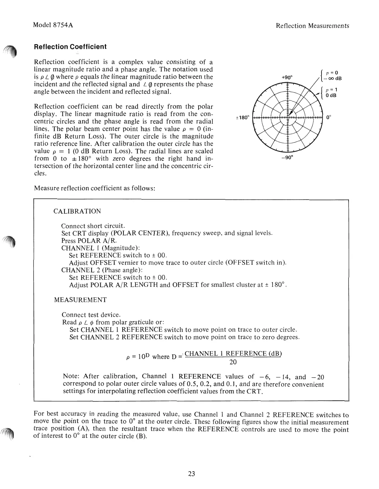
Reflection coefficient
can
be
read
directly
from
the
polar
display.
The
linear
magnitude
ratio
is
read
from
the
con-
centric circles
and
the
phase
angle is
read
from
the
radial
lines.
The
polar
beam
cente'r
point
has
the
value p = 0 (in-
finite dB
Return
Loss).
The
outer
circle is the
magnitude
ratio
reference line.
After
calibration
the
outer
circle
has
the
value
p'
= 1 (0 dB
Return
Loss).
The
radial
lines
are
scaled
from
0
to
± 180
0
with
zero
degrees
the
right
hand
in-
tersection
of
the
horizontal
center
line
and
the
concentric
cir-
cles.
v
Measure
reflection coefficient as follows:
CALIBRATION
Reflection Measurements
{
p
= 0
-oodB
Connect
short
circuit.
.Set
CRT
display
(POLAR
CENTER), frequency sweep,
and
signal levels.
Press
POLAR
AI
R.
CHANNEL 1 (Magnitude):
Set
REFERENCE
switch
to
± 00.
Adjust
OFFSET
vernier
to
move
trace
to
outer
circle
(OFFSET
switch in).
CHANNEL 2.(Phase angle):
Set
REFERENCE
switch
to
± 00.
Adjust
POLAR
AIR
LENGTH
and
OFFSET
for smallest cluster
at
± 180
0
•
MEASUREMENT
Connect
test
device.
Read p L ¢ from
polar
graticule or:
Set CHANNEL 1
REFERENCE
switch
to
move
point
on
trace
to
outer
circle.
Set CHANNEL 2
REFERENCE
switch
to
move
point
on
trace
to
zero degrees.
p =
IOD
where D
=!
CHANNEL I
REFERENCE
{dB)
20
Note:
After
calibration,
Channel
1
REFERENCE
values
of
- 6, - 14,
and
- 20
correspond
to
polar
outer
circle values
of
0.5, 0.2,
and
0.1,
and
are
therefore
convenient
settings
for
interpolating
reflection coefficient values
from
the
CRT.
For
best accuracy in reading
the
measured value, use
Channell
and
Channel 2
REFERENCE
switches
to
move
the
point
on
the
trace
to
0°
at
the
outer
circle. These following figures
show
the
initial
measurement
trace
position
(A),
then
the
resultant
trace
when
the
REFERENCE
controls
are used
to
move
the
point
of
interest
to
0°
at
the'
outer
circle (B).
23
Artisan Technology Group - Quality Instrumentation ... Guaranteed | (888) 88-SOURCE | www.artisantg.com