SWR,
standing
wave
ratio,
can
be calculated
from
Return
Loss using the
HP
Reflectometer
Calculator
(HP
P
/N
5952-0948)
or
these
equations:
Connect
test
device
Set
REFERENCE
switch
to
move
trace
to
reference position line.
Return
Loss =
REFERENCE
switch setting + trace displacement from reference
position
line.
f.
Model
8754A
.
dB
Reference
.~"'.
Frequency
MHz
Center
•
•
1 + P
1
-p
SWR=
p =
lOD
where D =
Return
Loss (dB)
-20
22
Connect
a
short
circuit.
Set
CRT
display, frequency sweep,
and
signal levels.
CHANNEL 1, select:
AIR.
Set
REFERENCE
switch
to
-00.
Adjust
OFFSET
vernier
to
move trace
to
reference position line
(OFFSET
switch in).
MEASUREMENT
CALIBRATION
For
example,
if
the
measured
magnitude
ratio
is
- 30 dB,
Return
Loss = 30 dB, P = 0.032,
and
the
SWR
is 1.07.
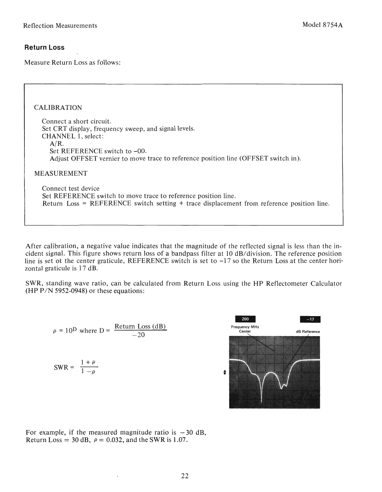
After
calibration,
a negative value indicates
that
the
magnitude
of
the reflected signal is less
than
the in-
cident signal. This figure shows
return
loss
of
a
bandpass
filter
at
10
dB/division.
The
reference
position
line is set
ot
the
center
graticule,
REFERENCE
switch is set
to
-17
so
the
Return
Loss
at
the
center
hori-
zontal
graticule
is
17 dB.
Measure
Return
Loss as follows:
Return Loss
Reflection Measurements
Artisan Technology Group - Quality Instrumentation ... Guaranteed | (888) 88-SOURCE | www.artisantg.com