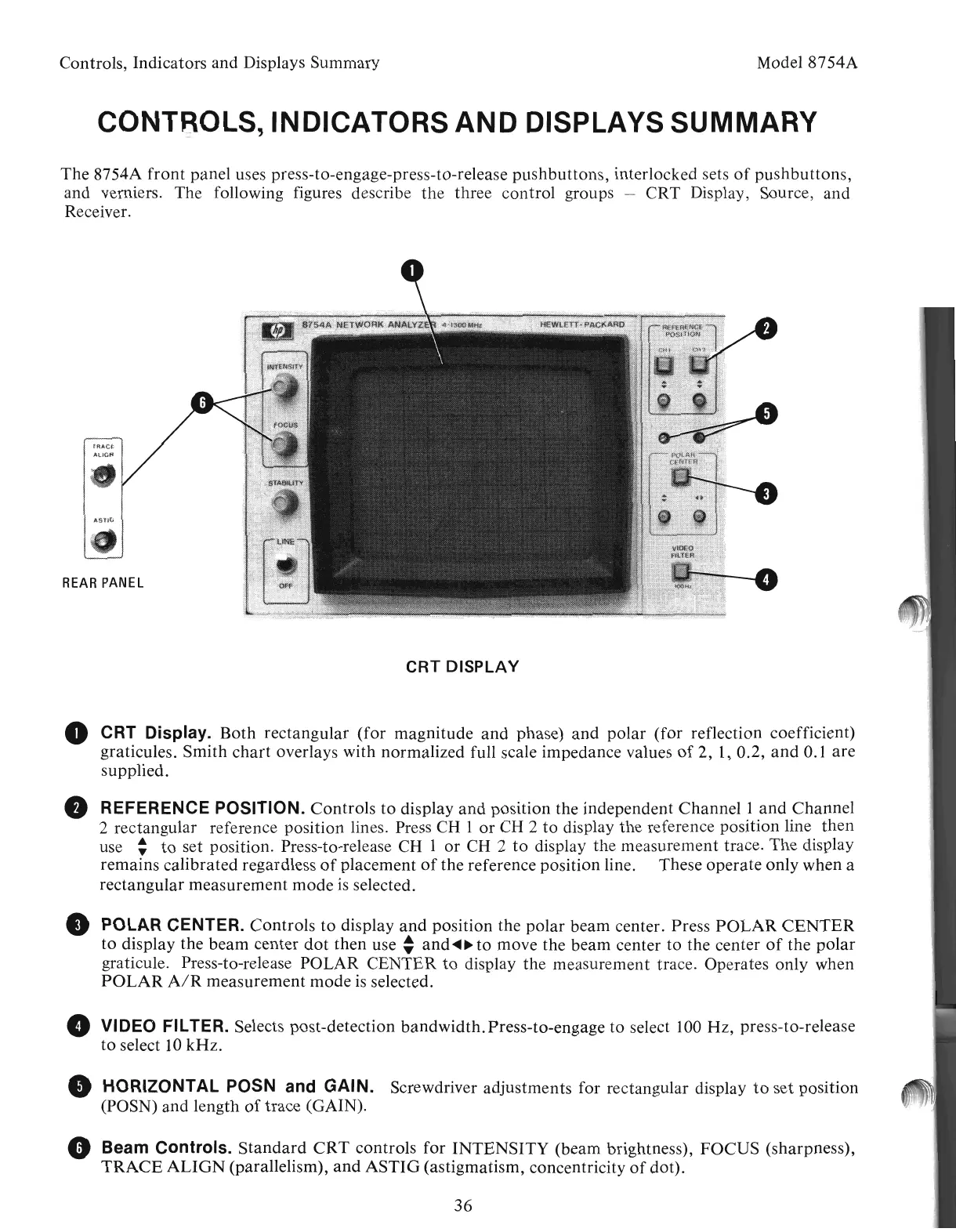
CRT
DISPLAY
36
Model 8754A
• HORIZONTAL POSN and' GAIN. Screwdriver adjustments for rectangular display
to
set position
(POSN) and length
of
trace (GAIN).
• VIDEO FILTER. Selects post-detection bandwidth.Press-to-engage to select 100 Hz, press-to-release
to
select
10
kHz
.
o Beam Controls.
Standard
CRT
controls for
INTENSITY
(beam brightness), FOCUS (sharpness),
TRACE
ALIGN
(parallelism),
and
ASTIG
(astigmatism, concentricity
of
dot).
• ·POLAR CENTER. Controls
to
display
and
position the polar beam center. Press
POLAR
CENTER
to
display the
beam
center
dot
then use
~
and
~~
to
move the beam center to the center
of
the
polar
, graticule. Press-to-release POLAR CENTER
to
display the measurement trace. Operates only when
POLAR
AIR
measurement
mode
is
selected.
CONTROLS, INDICATORS
AND
DISPLAYS SUMMARY
o CRT Display. Both rectangular (for magnitude
and
phase)
and
polar (for reflection coefficient)
graticules. Smith
chart
overlays with normalized full scale impedance values
of
2,
1,
0.2,
and
0.1 are
supplied.
• REFERENCE POSITION. Controls
to
display
and
position the independent
Channell
and
Channel
2 rectangular reference position lines. Press CH 1
or
CH 2
to
display the reference position line
then
use :
to
set position. Press-to-release CH 1
or
CH 2
to
display the measurement trace. The display
remains calibrated regardless
of
placement
of
the reference position line. These operate only when a
rectangular measurement mode
is
selected.
REAR
PANEL
The 8754A
front
panel uses press-to-engage-press-to-release pushbuttons, interlocked sets
of
pushbuttons,
and verniers. The following figures describe the three control groups - CRT Display, Source, and
Receiver.
Controls, Indicators and Displays Summary
Artisan Technology Group - Quality Instrumentation ... Guaranteed | (888) 88-SOURCE | www.artisantg.com