Model
8754A
Controls, Indicators and Displays Summary
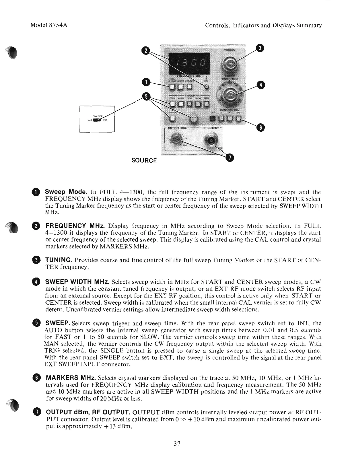
o Sweep Mode.
In
FULL
4-1300,
the full frequency range
of
the
instrument
is
swept
and
the
FREQUENCY
MHz
display shows the frequency
of
the
Tuning
Marker.
START
and
CENTER
select
the
Tuning Marker frequency
as
the
start
or
center
frequency
of
the
sweep selected
by
SWEEP WIDTH
MHz.
• FREQUENCY MHz. Display frequency in
MHz
according
to
Sweep
Mode
selection. In
FULL
4-1300
it
displays
the
frequency
of
the
Tuning Marker. In START
or
CENTER,
it
displays
the
start
or
center frequency
of
the selected sweep. This display
is
calibrated using the
CAL
control
and
crystal
markers
selected by
MARKERS
MHz
.
•
TUNING.
Provides coarse
and
fine
control
of
the full sweep
Tuning
Marker
or
the
START
or
CEN-
TER
frequency.
• SWEEP WIDTH MHz. Selects sweep width in
MHz
for
START
and
CENTER
sweep modes, a
CW
mode
in which the
constant
tuned
frequency
is
output,
or
an
EXT
RF
mode
switch selects
RF
input
from an external source. Except for
the
EXT
RF
position, tllis control
is
active only when START
or
CENTER
is selected. Sweep width is calibrated when the small internal
CAL
vernier
is
set to fully
CW
detent.
Uncalibrated
vernier settings allow intermediate sweep width selections.
• SWEEP. Selects sweep trigger and sweep time. With
the
rear panel sweep switch set
to
INT,
the
AUTO
button
selects
the
internal sweep generator with sweep times between 0.01
and
0.5 seconds
for FAST
or
1
to
50 seconds for SLOW. The vernier controls sweep time within these ranges. With
MAN selected,
the
vernier controls
the
CW
frequency
output
within
the
selected sweep width. With
TRIG
selected,
the
SINGLE
button
is pressed
to
cause a single sweep
at
the
selected sweep time.
With
the
rear panel SWEEP switch set
to
EXT,
the
sweep is controlled
by
the
signal
at
the
rear panel
~XT
SWEEP INPUT connector.
• MARKERS MHz. Selects crystal
markers
displayed
on
the trace
at
50
MHz,
10
MHz,
or
1
MHz
in-
tervals used
for
FREQUENCY
MHz
display
calibration
and
frequency measurement.
The
50
MHz
and
10
MHz
markers
are
active in all
SWEEP
WIDTH
positions
and
the 1
MHz
markers
are
active
for sweep widths
of
20
MHz
or
less.
e OUTPUT dBm, RF OUTPUT.
OUTPUT
dBm
controls internally leveled
output
power
at
RF
OUT-
PUT
connector.
Output
level is calibrated
from
0
to
+
10
dBm
and
maximum
uncalibrated
power out-
put
is
approximately
+
13
dBm.
37
Artisan Technology Group - Quality Instrumentation ... Guaranteed | (888) 88-SOURCE | www.artisantg.com