MEASUREMENT
18
,i
•
dB Reference
Model
8754A
/'f"
I
I
I
I
Adjust
TUNING
to
move
lower
-3dB
point
to
center
- ..
•
,.1'1
Frequency
MHz
Center
•
•
...........
~
\
\
\
\
Adjust
TUNING
to
move
upper
-3
dB
point
to
center
....
Increase REFERENCE
value
-03
to
move
trace
up
v
........,
I
I
\
V
\
\
\
_..
/'
i'\
I
I
\
I
\
--
Adjust
'~
~
to
move
point
to
center graticule
Channell
or
Channel 2, select:
Connect a
"through."
Set CRT display, frequency sweep, and signal levels.
CALIBRATION
Relative Measurements
To measure the difference between two points
on
the
trace, use the channel REFERENCE POSITION
~
control
to
move the first
point
to
a horizontal graticule,
then
use REFERENCE switch
to
move
the
second
point
to
the same line. The change from
the
initial value
to
the second value for REFERENCE
is
the
difference between the
two
points. Note
that
scale division must
not
be changed during this sequence.
After
measurement, press channel
REFERENCE
POSITION
and
use
~
to
move the reference line back
to
the original position.
Connect test device.
Set REFERENCE switch
to
move
point
of
interest
on
trace
to
reference position line.
Magnitude ratio
= REFERENCE switch setting + trace displacement from reference position
line.
B/R.
Set REFERENCE switch
to
± 00.
Adjust OFFSET vernier
to
move trace
to
reference position line (OFFSET switch in).
This technique can be used
to
read relative values between any two points on the trace.
For
example,
the
frequency
at
the
-3
dB points
of
a filter response can be measured
as
shown in this figure.
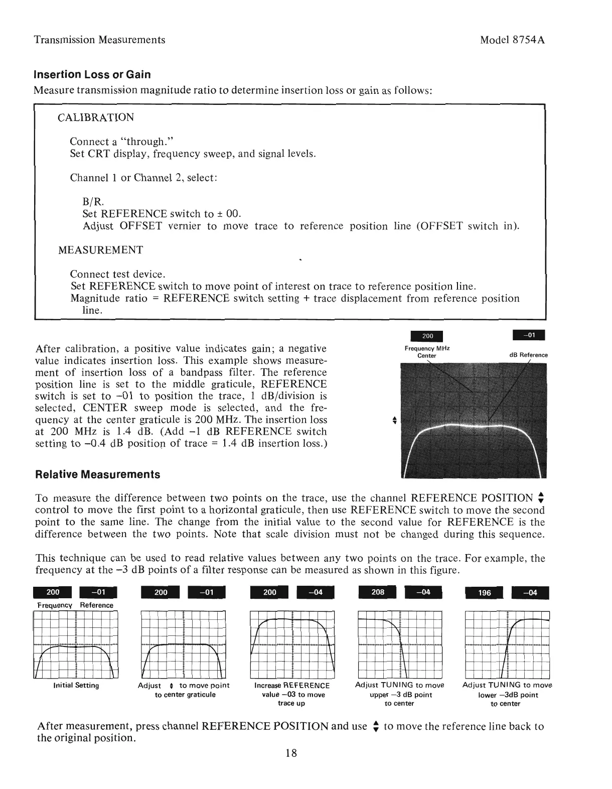
After calibration, a positive value indicates gain; a negative
value indicates insertion loss. This example shows measure-
ment
of
insertion loss
of
a bandpass filter. The reference
position line
is
set
to
the
middle graticule, REFERENCE
switch
is
set
to
-01
to
position the trace, 1 dB/division
is
selected, CENTER sweep
mode
is
selected, and
the
fre-
quency
at
the
center graticule is 200 MHz. The insertion loss
at 200
MHz
is
1.4 dB. (Add
-1
dB
REFERENCE switch
setting
to
-0.4
dB
positiop
of
trace = 1.4
dB
insertion loss.)
/'
~
I
\
I
~
II
\
Transmission Measurements
Initial
Setting
Insertion Loss or Gain
Measure transmission magnitude
ratio
to
determine insertion loss
or
gain as follows:
--
Frequency Reference
Artisan Technology Group - Quality Instrumentation ... Guaranteed | (888) 88-SOURCE | www.artisantg.com