Model
8754A
Transmission Measurements
TRANSMISSION MEASUREMENTS
The
8754Ameasures
transmission
insertion
loss
or
gain
(B/R)
using
either
Channell
or
Channel 2,
and
measures
insertion
phase (PHASE
B/R)
using Channel 2. The calibration
standard
for transmission
measurements
is
a
"through"
connection
(connect
together
the
points
at
which
the
test
device will
be
con-
nected).
Complete
transmission
calibration
sets
the
magnitude
ratio
between the
Rand
B
inputs
to
0 dB
and
the
phase angle
to
0° over
the
frequency range
of
interest.
The
following paragraphs describe trans-
mission
magnitude
ratio
and
insertion
phase calibration
and
measurement
in
separate sequences,
but
the
sequences
can
be
combined
by
using
Channell
for
magnitude
and
Channel
2
for
phase.
Equal
--.a
---
I Length
Longer
Transmission Return
Tes
9
Test p
DeVice
Connect
TOgether.J'
To
Calibrate
Reflected
To
Input
A
8502
Incident
To
Input
R
RF
Input
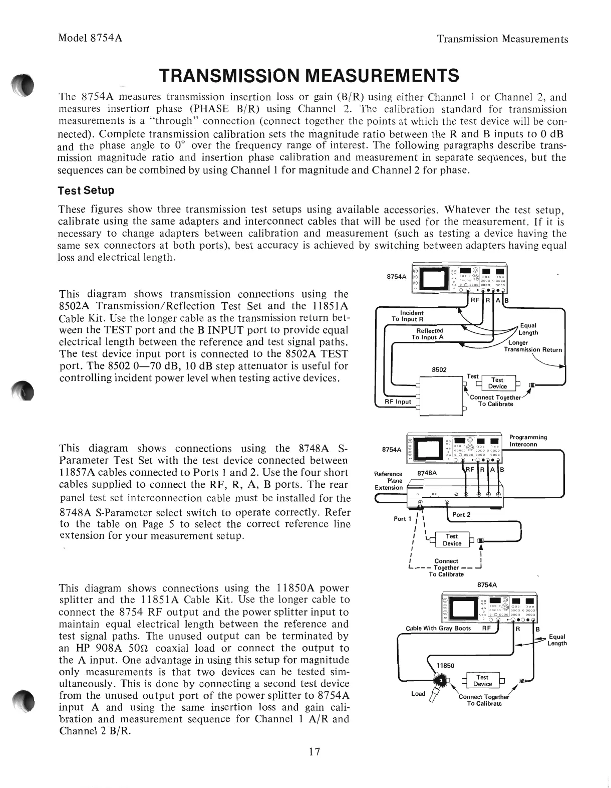
This
diagram
shows
transmission
connections
using
the
8502A
Transmission/Reflection
Test
Set
and
the
11851A
Cable Kit. Use
the
longer cable as
the
transmission
return
bet-
ween
the
TEST
port
and
the
B
INPUT
port
to
provide
equal
electrical
length
between
the
reference
and
test signal
paths.
The
test
device.input
port
is
connected
to
the 8502A
TEST
port.
The
8502
0-70
dB, 10 dB
step
attenuator
is useful
for
controlling
incident
power
level
when
testing active devices.
Test Setup
These
figures
show
three
transmission
test setups using available accessories.
Whatever
the test
setup,
calibrate
using
the
same
adapters
and
interconnect
cables
that
will be used
for
the
measurement.
If
it
is
necessary
to
change
adapters
between
calibration
and
measurement
(such as testing a device having
the
same sex
connectors
at
both
ports),
best accuracy is achieved
by
switching
between
adapters
having equal
loss
and
electrical length.
8748A
'\
,
\<
I
"
~~
Test h
,
~
Device
~
lAJ!-----'
I I
, Connect I
L Together
__
-J
To
Calibrate
O
~
Programming
8754A
~@:
0
:0:
~@
~
0
~
II--In_te_rc_o_nn
__
........
o
00
a 0
0000
0000 0000
o 0 0
••
RF R A B
This
diagram'
shows
connections
using
the
8748A S-
Parameter
Test
Set
with
the
test device
connected
between
11857A cables
connected
to
Ports
1
and
2. Use
the
four
short
cables
supplied
to
connect
the
RF,
R,
A,
B
ports.
The
rear
panel
test
set
interconnection
cable
must
be installed for
the
8748A
S-Parameter select
switch
to
operate
correctly.
Refer
to
the
table
on
Page 5
to
select
the
correct
reference line
extension
for
your
measurement
setup.
8754A
This diagram shows
connections
using
the
11850A
power
splitter
and
the
11851A Cable Kit. Use
the
longer cable
to
connect
the
8754
RF
output
and
the
power
splitter
input
to
maintain
equal electrical
length
between
the
reference
and
test
signal paths. The
unused
output
can be
terminated
by
an HP
908A
san
coaxial
load
or
connect
the
output
to
the
A
input.
One
advantage in using this
setup
for
magnitude
only
measurements
is
that
two
devices can be
tested
sim-
ultaneously. This is
done
by
connecting
a second
test
device
from
the
unused
output
port
of
the
power
splitter
to
8754A
input
A
and
using
the
same
insertion
loss
and
gain cali-
bration
and
measurement
sequence
for
Channel 1
AIR
and
Channel 2 B/R.
Load
11850
,~D~~~eP/
Connect Together
To
Calibrate
Equal
Length
17
Artisan Technology Group - Quality Instrumentation ... Guaranteed | (888) 88-SOURCE | www.artisantg.com