Model
8754A
Quick Reference Guide
QUICK REFERENCE
GUIDE
(Cont'd)
23
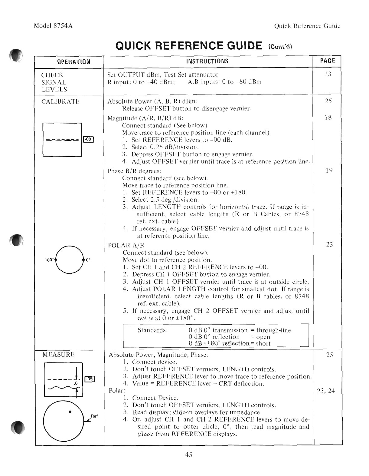
OPERATION
CHECI(
SIGNAL
LEVELS
CALIBRATE
-
....
----~-
~
INSTRUCTIONS
PAGE
Set OUTPUT dBm, Test Set
attenuator
13
R
input:
0
to
-40
dBm; A,B inputs: 0
to
-80
dBm
Absolute Power (A,
B,
R) dBm: 25
Release
OFFSET
button
to
disengage vernier.
Magnitude (A/R,
B/R)
dB: 18
Connect
standard
(See below)
Move trace
to
reference position line (each channel)
1.
Set
REFERENCE
levers
to
-00
dB.
2. Select
0.25
dB/division.
3. Depress
OFFSET
button
to
engage vernier.
4. Adjust
OFFSET
vernier until trace
is
at
reference position line.
Phase
B/R
degrees: 19
Connect
standard
(see below).
Move trace
to
reference position line.
1.
Set
REFERENCE
levers
to
-00
or
+180.
2. Select 2.5 deg./division.
3. Adjust LENGTH controls for horizontal trace.
If
range
is
in-
sufficient, select cable lengths
(R
or
B Cables,
or
8748
ref.
ext.
cable)
4.
If
necessary, engage
OFFSET
vernier and adjust until trace
is
at
reference position line.
POLAR
A/R
Connect
standard
(see below).
Move
dot
to
reference position.
1.
Set CH 1 and CH 2
REFERENCE
levers
to
-00.
2. Depress CH 1
OFFSET
button
to
engage vernier.
3. Adjust CH 1
OFFSET
vernier until trace
is
at
outside circle.
4. Adjust POLAR LENGTH
control
for smallest
dot.
If
range
is
insufficient, select cable lengths
(R
or
B cables,
or
8748
ref.
ext.
cable).
5.
If
necessary, engage CH 2
OFFSET
vernier and adjust until
dot
is
at
0
or
± 180° .
Standards:
odB 0° transmission = through-line
odB 0° reflection =
open
odB ± 180° reflection =
short
MEASURE
•
Ref
Absolute Power, Magnitude, Phase:
1.
Connect
device.
2.
Don't
touch
OFFSET
verniers, LENGTH controls.
3. Adjust
REFERENCE
lever
to
move trace
to
reference position.
4. Value
=
REFERENCE
lever +
CRT
deflection.
Polar:
1.
Connect
Device.
2.
Don't
touch
OFFSET
verniers, LENGTH controls.
3. Read display; slide-in overlays for impedance.
4. Or, adjust CH 1 and CH 2
REFERENCE
levers
to
move de-
sired
point
to
outer
circle, 0°,
then
read magnitude and
phase from
REFERENCE
displays.
45
25
23, 24
Artisan Technology Group - Quality Instrumentation ... Guaranteed | (888) 88-SOURCE | www.artisantg.com