362
HP
8904A
Option
001
Enhancements
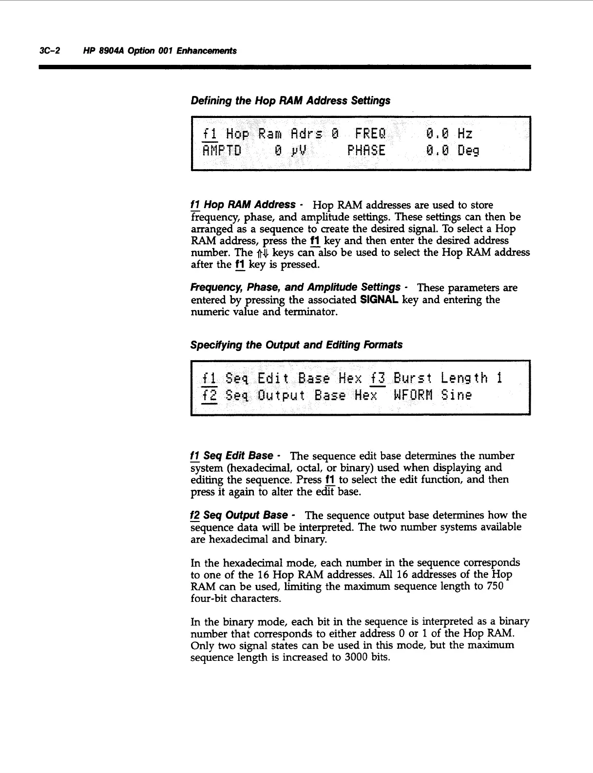
Defining the Hop
RAM
Address Settings
-
f7
Hop
RAM
Address
-
Hop
RAM
addresses are used to store
frequency, phase, and amplitude settings. These settings can then be
arranged as a sequence to create the desired signal.
To
select
a
Hop
RAM
address, press the
fl
key and then enter the desired address
number. The
after the
-
fl
key
is
pressed.
Fiequency, Phase, and Amplitude Settings
-
These parameters are
entered by pressing the assoaated
SIGNAL
key and entering the
numeric value and terminator.
keys caralso be used to select the Hop
RAM
address
Specifying the Output and Editing
hrmats
-
f7
Seq
Edit
Base
-
The sequence edit base determines the number
system (hexadecimal, octal, or binary) used when displaying and
editing the sequence. Press
fl
to select the edit function, and then
press it again to alter the efibase.
f2
-
Seq Output Base
-
The sequence output base determines how the
sequence data
will
be interpreted. The
two
number systems available
are hexadecimal and binary.
In
the hexadecimal mode, each number in the sequence corresponds
to one of the
16
Hop
RAM
addresses.
All
16
addresses of the Hop
RAM
can be used,
limiting
the maximum sequence length to
750
four-bit characters.
In the binary mode, each bit in the sequence is interpreted as
a
binary
number that corresponds to either address
0
or
1
of
the Hop
RAM.
Only
two
signal states can
be
used
in
this mode, but the maximum
sequence length is increased to
3000
bits.
Artisan Technology Group - Quality Instrumentation ... Guaranteed | (888) 88-SOURCE | www.artisantg.com