c
w
es04~
MULTIFUNCTION
SYNTHESIZER
Model 8904A Performance Tests
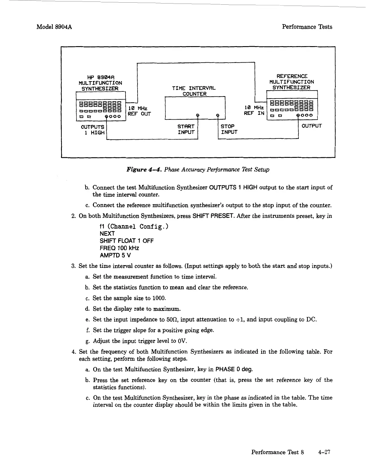
Figure
4-4.
Phase
Accuracy
Performance Test
Setup
OUTPUTS
1
HIGH
I
I
TIME INTERVRL
COUNTER
STflRT
INPUT INPUT
REFERENCE
MULTIFUNCTION
SYNTHESIZER
OUTPUT
7-
b. Connect the
test
Multifunction Synthesizer
OUTPUTS
1
HIGH
output to the
start
input of
the time interval counter.
c. Connect the reference multifunction synthesizer's output
to
the stop input of the counter.
2.
On both Multifunction Synthesizers, press
SHIFT
PRESET.
After the instruments preset, key in
fl
(Channel Config.)
NEXT
SHIFT
FLOAT
1
OFF
FREQ
100
kHz
AMPTD
5
V
3.
Set the time interval counter
as
follows. (Input settings apply to both the
start
and stop inputs.)
a. Set the measurement function to time interval.
b. Set the statistics function
to
mean and clear the reference.
c. Set the sample size to
1000.
d. Set the display rate to maximum.
e. Set the input impedance to
50Q,
input attenuation to
tl,
and input coupling to
DC.
f.
Set the trigger slope for a positive going edge.
g.
Adjust the input trigger level to
OV.
4.
Set the frequency of both Multifunction Synthesizers as indicated in the following table. For
each setting, perform the following steps.
a. On the test Multifunction Synthesizer, key in
PHASE
0
deg.
b. Press the set reference key on the counter (that is, press the set reference key of the
statistics functions).
c.
On the test Multifunction Synthesizer, key in the phase as indicated in the table. The time
interval on the counter display should be within the limits given in the table.
Performance Test
8
4-27
Artisan Technology Group - Quality Instrumentation ... Guaranteed | (888) 88-SOURCE | www.artisantg.com