EasyManuals Logo

HP dx7500 - Microtower PC User Manual

HP dx7500 - Microtower PC
200 pages
To Next Page IconTo Next Page
To Previous Page IconTo Previous Page
Page #66 background imageLoading...
Page #66 background image
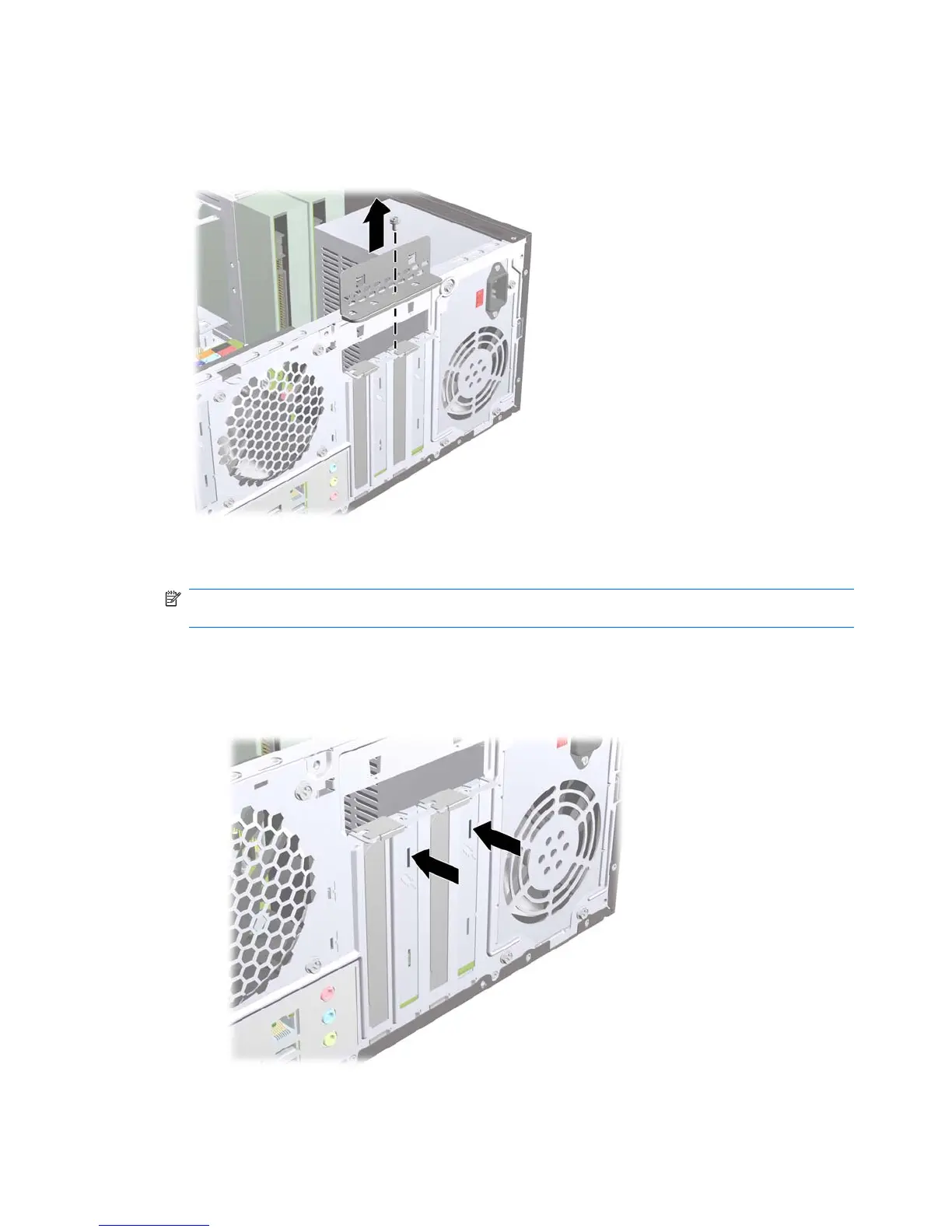
4. On the rear of the computer, a slot cover lock secures the expansion card brackets in place.
Remove the screw from the slot cover lock then slide the slot cover lock up to remove it from the
chassis.
Figure 7-8 Opening the Slot Cover Lock
5. Before installing an expansion card, remove the expansion slot cover or the existing expansion
card.
NOTE: Before removing an installed expansion card, disconnect any cables that may be attached
to the expansion card.
a. If you are installing an expansion card in a vacant socket, you must use a flatblade screwdriver
to pry out the metal shield on the rear panel that covers the expansion slot. Be sure to remove
the appropriate shield for the expansion card you are installing.
Figure 7-9 Removing an Expansion Slot Cover
56 Chapter 7 Removal and Replacement Procedures Microtower (MT) Chassis

Table of Contents

Other manuals for HP dx7500 - Microtower PC

Questions and Answers:

Question and Answer IconNeed help?

Do you have a question about the HP dx7500 - Microtower PC and is the answer not in the manual?

HP dx7500 - Microtower PC Specifications

General IconGeneral
MemoryUp to 8 GB DDR2 SDRAM
Form FactorMicrotower
Power Supply300W
ProcessorIntel Core 2 Duo, Intel Pentium Dual-Core, Intel Celeron
StorageSATA hard drives up to 500 GB
Optical DriveDVD-ROM or DVD+/-RW
GraphicsIntegrated Intel Graphics Media Accelerator 3100, Optional discrete graphics cards
AudioIntegrated High Definition Audio
NetworkIntegrated Gigabit Ethernet
Expansion Slots1 PCI Express x16, 2 PCI Express x1, 1 PCI
PortsUSB 2.0, serial, parallel, VGA, audio in/out
Operating SystemWindows Vista Business, Windows XP Professional, FreeDOS
WeightApprox. 22 lbs (10 kg)

Related product manuals