System board
The system board is secured with nine Torx screws.
To remove the system board:
1. Prepare the computer for disassembly (see Preparing to disassemble the computer on page 19).
2. Remove the rear port cover (see Removing the rear port cover on page 19).
3. Remove the stand (see Stands on page 20).
4. Remove the access panel (see Access panel on page 21).
5. Remove the memory modules (see Memory on page 28).
6. Remove the M.2 solid-state drive (see M.2 solid-state drive on page 26).
7. Remove the WLAN module (see WLAN module on page 31).
8. Remove the VESA bracket/fan assembly (see VESA mounting bracket/fan assembly on page 43.
9. Remove the heat sink (see Heat sink on page 35).
10. Remove the processor (see Processor on page 38.
11. Remove the hard drive cage (see Hard drive cage on page 49.
12. Remove the I/O bracket (see I/O bracket on page 48.
13. Remove the rear I/O cover (see Rear I/O cover on page 47.
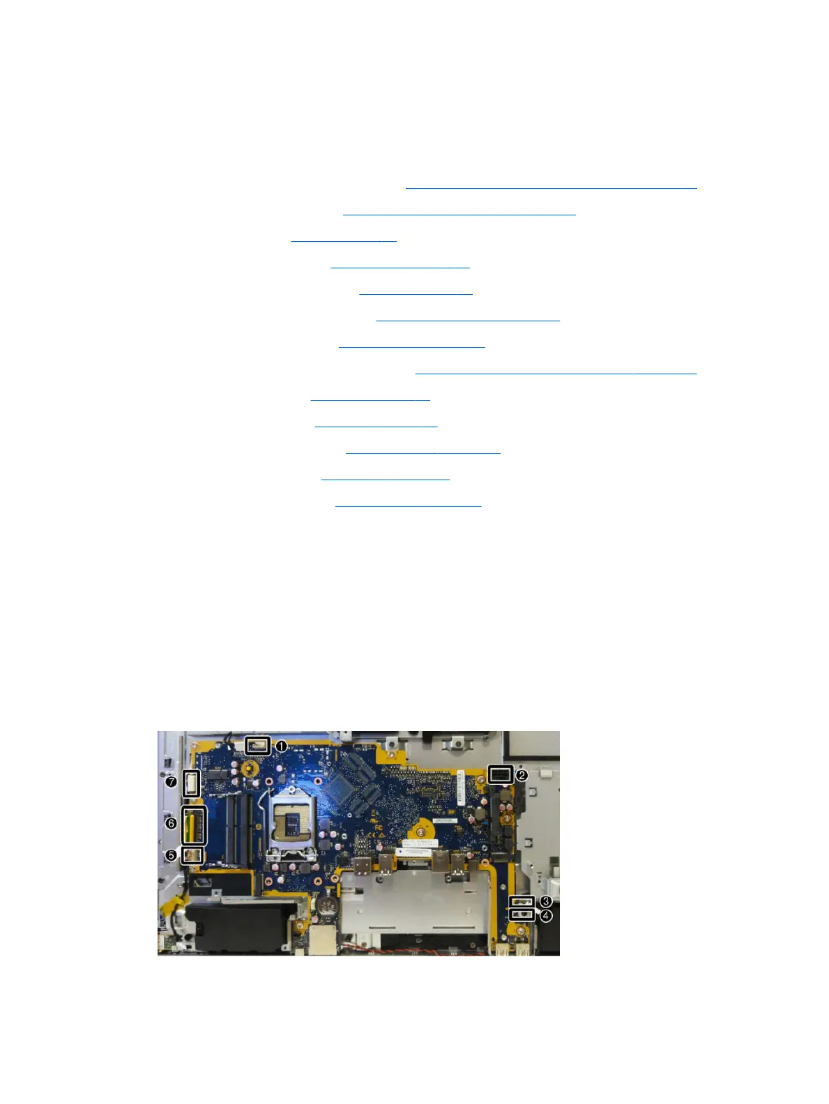
14. Disconnect all cables from the system board, noting their location for reinstallation:
(1): Camera cable
(2): Power supply cable
(3): Front audio cable
(4): Speaker cable
(5): Front panel cable
(6): Converter cable
(7): LVDS (display) cable
50 Chapter 4 Removal and Replacement Procedures
 Loading...