Bottom cover and rubber feet
Table 5-1 Bottom cover and rubber feet descriptions and part numbers
Description Spare part number
Bottom cover L52805-001
Rubber Foot Kit L52666-001
▲ Prepare the computer for disassembly (Preparation for disassembly on page 26).
Remove the bottom cover and rubber feet:
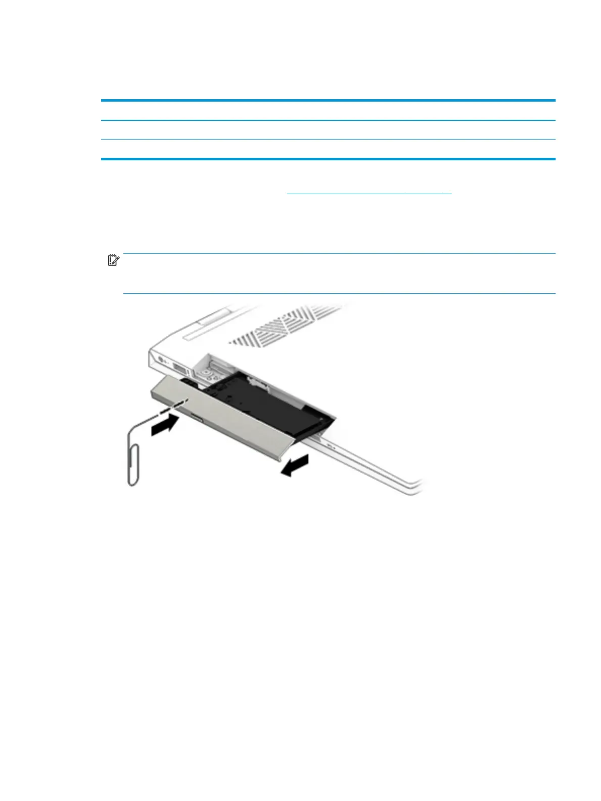
1. Insert a very thin paper clip or similar tool into the release hole in the optical drive bezel to release the
drive tray.
IMPORTANT: You must release the drive tray to gain access to the screw in the drive bay that secures
the bottom cover. You cannot remove the optical drive in this step. You must remove the bottom cover
before you can remove the optical drive from the computer.
2. Peel the two upper rubber feet o the bottom of the computer (1).
3. Remove the four Phillips M2.5 × 4.0 screws from under each foot (2).
4. Remove the Phillips broadhead M2.0 × 2.0 screw from the optical drive bay.
5. Remove the two Torx T8 2.5 × 14.0 screws from each side of the computer (4).
Component replacement procedures 27
 Loading...