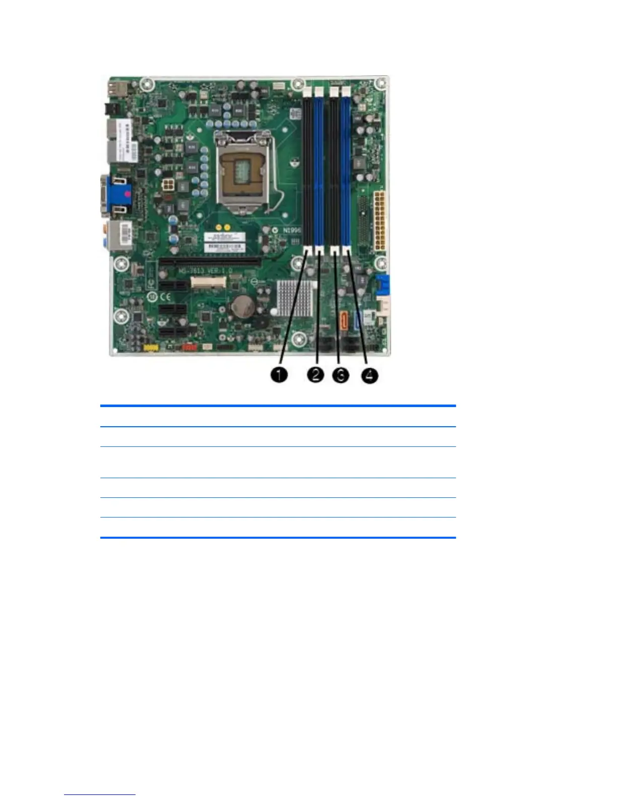
Figure 6-5 DIMM Socket Locations – HP Pro 3130
Table 6-3 DIMM Socket Locations – HP Pro 3130
Item Description Socket Color Insertion Order
1 XMM1 socket, Channel B Black 3
2 XMM2 socket, Channel B
(populate first)
Blue 1
3 XMM3 socket, Channel A Black 4
4 XMM4 socket, Channel A Blue 2
NOTE: A DIMM must occupy the XMM2 socket.
The system will automatically operate in single channel mode, dual channel mode, or flex mode,
depending on how the DIMMs are installed.
●
The system will operate in single channel mode if the DIMM sockets are populated in one channel
only.
●
The system will operate in a higher-performing dual channel mode if the total memory capacity of
the DIMMs in Channel A is equal to the total memory capacity of the DIMMs in Channel B. The
technology and device width can vary between the channels. For example, if Channel A is
populated with two 1-GB DIMMs and Channel B is populated with one 2-GB DIMM, the system
will operate in dual channel mode.
94 Chapter 6 Removal and Replacement Procedures Small Form Factor (SFF) Chassis
 Loading...