Table 4-14 System board descriptions and part numbers (continued)
Description Spare part number
For use in models with a NetClone BIOS with the following processors: 14000 series, 300 N81936-601
NOTE: All system board spare part kits include replacement thermal material.
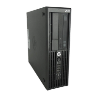
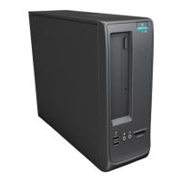
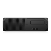
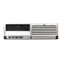
System board appearance can vary.
Before removing the system board, follow these steps:
1. Prepare the computer for disassembly (see Preparation for disassembly on page 22).
2. Remove the access panel (see Access panel on page 23).
3. Remove the optical drive (see Optical drive on page 25).
4. Remove the front bezel (see Front bezel on page 26).
5. Remove the WLAN module (see WLAN module on page 30).
6. Remove the expansion card (see Expansion card on page 37).
7. Remove the fan hood (see Fan vent on page 39).
8. Remove the heat sink (see Heat sink on page 40).
Remove the system board:
1. Disconnect the cables from the following connectors on the system board:
● Power supply P3 cable
● Fan cable
● Drive data cables
● Drive power cable
● Power supply P1 cable
● Speaker cable
● Power supply P2 cable
46
Chapter 4 Removal and replacement procedures

 Loading...