Component identification 94
Switch Default Function
2
Off Off = System configuration can be
changed
On = System configuration is locked
5
Off Off = Power-on password is enabled
On = Power-on password is disabled
6
Off Off = No function
On = ROM reads configuration as
invalid
3, 4, 7, 8, 9,
10, 11, 12
— Reserved
When the system maintenance switch position 6 is set to the On position, the system is prepared to erase all
system configuration settings from both CMOS and NVRAM.
CAUTION: Clearing CMOS and/or NVRAM deletes configuration information. Be sure to
properly configure the server or data loss could occur.
NMI functionality
An NMI crash dump creates a crash dump log before resetting a system which is not responding.
Crash dump log analysis is an essential part of diagnosing reliability problems, such as failures of operating
systems, device drivers, and applications. Many crashes freeze a system, and the only available action for
administrators is to restart the system. Resetting the system erases any information which could support
problem analysis, but the NMI feature preserves that information by performing a memory dump before a
system reset.
To force the system to invoke the NMI handler and generate a crash dump log, do one of the following:
• Use the iLO Virtual NMI feature.
• Short the NMI header ("System board components" on page 92).
For more information, see the HP website (http://www.hp.com/support/NMI).
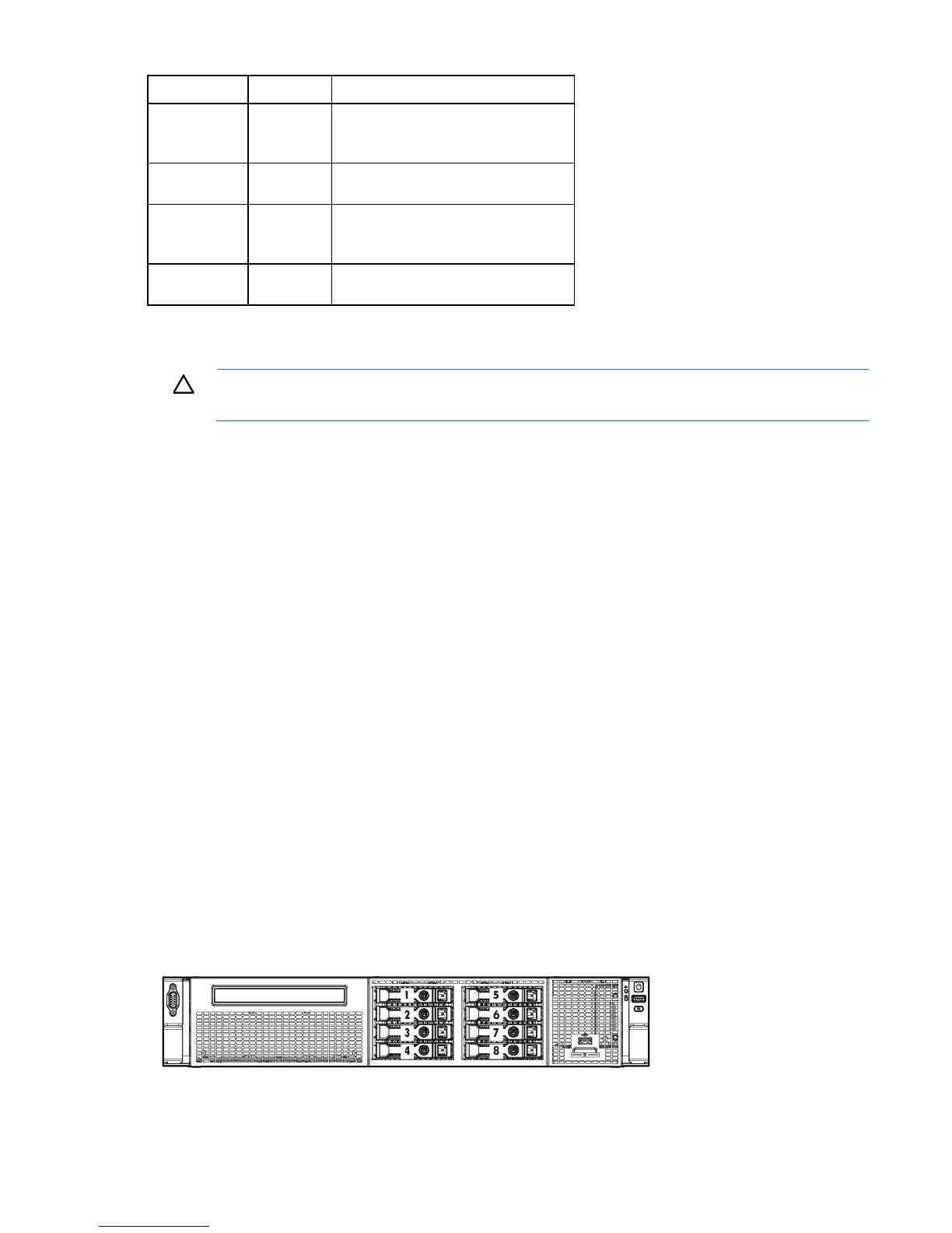
Drive numbering
In an 8-bay drive cage, when only one SATA cable is connected, the server can only support a 4-drive
configuration. In this configuration, drive bays 1 through 4 are populated, while drive bays 5 through 8 have
drive blanks.
When the two-port SATA cable option is connected, the server supports a 6-drive configuration. In this
configuration, drive bays 1 through 6 are populated, while drive bays 7 and 8 have drive blanks.
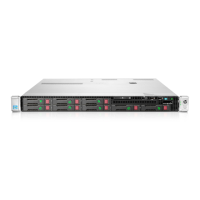
• 8-bay SFF drive model
 Loading...