Section III
Model 4342A
Table 3-l
Table 3-1.
Methods of Connecting Unknown.
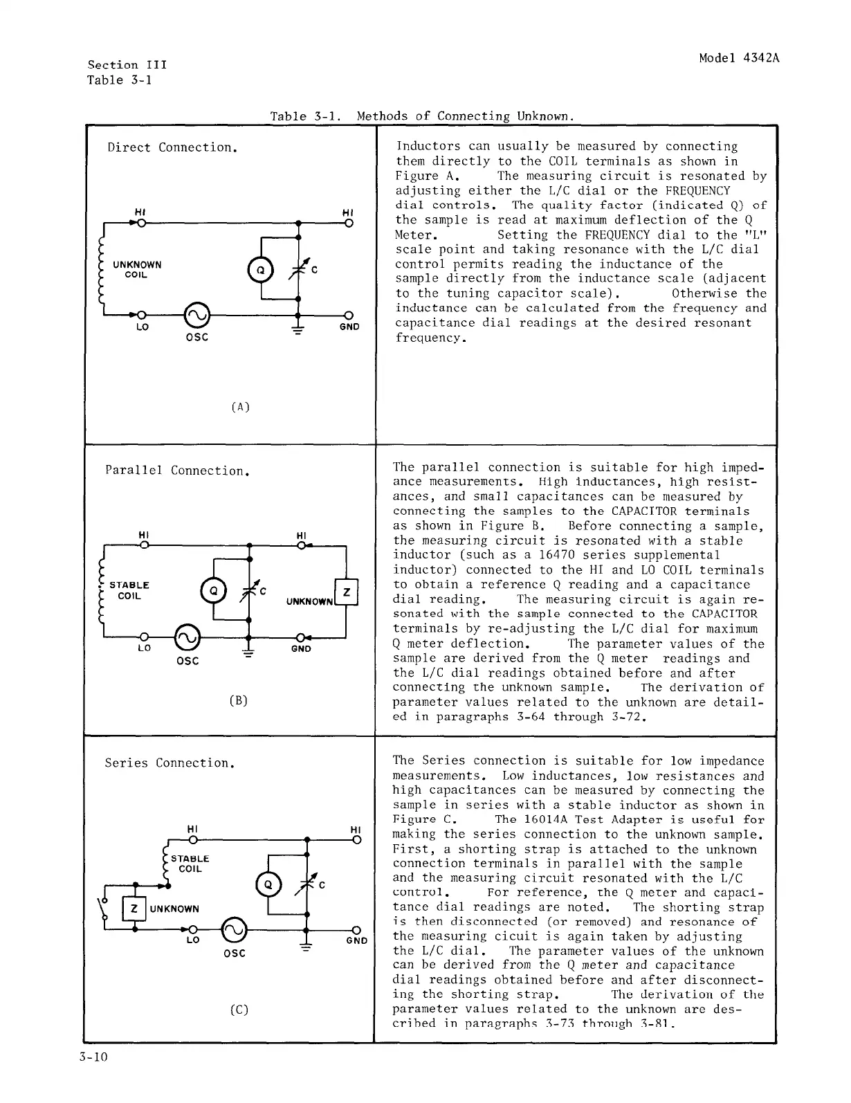
Direct Connection.
Inductors can usually be measured by connecting
them directly to the COIL terminals as shown in
Figure A. The measuring circuit is resonated by
adjusting either the L/C dial or the FREQUENCY
HI HI
dial controls. The quality factor (indicated Q) of
0
the sample is read at maximum deflection of the Q
Meter. Setting the FREQUENCY dial to the "L"
scale point and taking resonance with the L/C dial
control permits reading the inductance of the
sample directly from the inductance scale (adjacent
to the tuning capacitor scale). Otherwise the
0
inductance can be calculated from the frequency and
I
E
GND
capacitance dial readings at the desired resonant
osc frequency.
Parallel Connection.
The parallel connection is suitable for high imped-
ance measurements. High inductances, high resist-
ances, and small capacitances can be measured by
connecting the samples to the CAPACITOR terminals
HI
-
v-
UNKNOWN
as shown in Figure B. Before connecting a sample,
the measuring circuit is resonated with a stable
inductor (such as a 16470 series supplemental
inductor) connected to the HI and LO COIL terminals
to obtain a reference Q reading and a capacitance
dial reading. The measuring circuit is again re-
sonated with the sample connected to the CAPACITOR
b
terminals by re-adjusting the L/C dial for maximum
LO
ON0
Q meter deflection.
The parameter values of the
osc -
sample are derived from the Q meter readings and
the L/C dial readings obtained before and after
connecting the unknown sample. The derivation of
(Bl
parameter values related to the unknown are detail-
ed in paragraphs 3-64 through 3-72.
Series Connection.
The Series connection is suitable for low impedance
measurements. Low inductances, low resistances and
high capacitances can be measured by connecting the
sample in series with a stable inductor as shown in
HI
Figure C.
HI
The 16014A Test Adapter is useful for
h
making the series connection to the unknown sample.
First,
a shorting strap is attached to the unknown
connection terminals in parallel with the sample
and the measuring circuit resonated with the L/C
control. For reference, the Q meter and capaci-
tance dial readings are noted. The shorting strap
0
is then disconnected (or removed) and resonance of
GND
the measuring cicuit is again taken by adjusting
osc
the L/C dial.
The parameter values of the unknown
can be derived from the Q meter and capacitance
dial readings obtained before and after disconnect-
ing the shorting strap. The derivation of the
(Cl
parameter values related to the unknown are des-
cribed in paragraphs 3-73 through 3-81.
3-10
 Loading...


