Model 4342A
Direct Connection Measurements
Section III
Paragraphs 3-30 to 3-34
3-30. BASIC Q METER MEASUREMENTS.
3-31. QUALITY FACTOR AND INDUCTANCE
MEASLREMENT~ (DIRECT C~NNK-U~N).
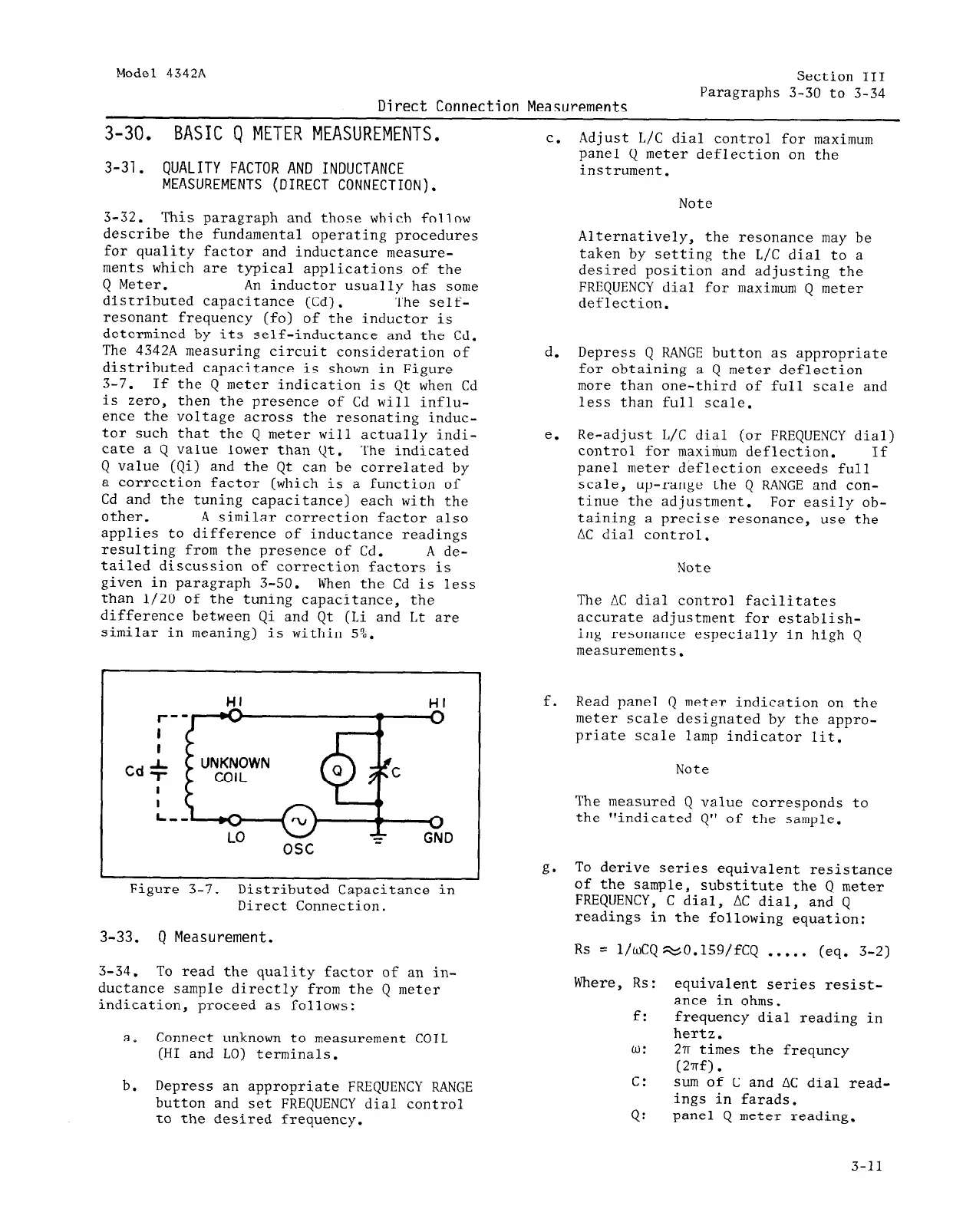
3-32. This paragraph and those which follow
describe the fundamental operating procedures
for quality factor and inductance measure-
ments which are typical applications of the
Q Meter. An inductor usually has some
distributed capacitance (Cd).
The self-
resonant frequency (fo) of the inductor is
determined by its self-inductance and the Cd.
The 4342A measuring circuit consideration of
distributed capacitance is shown in Figure
3-7. If the Q meter indication is Qt when Cd
is zero, then the presence of Cd will influ-
ence the voltage across the resonating induc-
tor such that the Q meter will actually indi-
cate a Q value lower than Qt. The indicated
Q value (Qi) and the Qt can be correlated by
a correction factor (which is a function of
Cd and the tuning capacitance) each with the
other. A similar correction factor also
applies to difference of inductance readings
resulting from the presence of Cd.
A de-
tailed discussion of correction factors is
given in paragraph 3-50. When the Cd is less
than l/20 of the tuning capacitance, the
difference between Qi and Qt (Li and Lt are
similar in meaning) is within 5%.
r-
I
I
Cd +
I
I
L,
0
GND
Figure 3-7.
Distributed Capacitance in
Direct Connection.
3-33. Q Measurement.
3-34.
To read the quality factor of an in-
ductance sample directly from the Q meter
indication, proceed as follows:
a. Connect unknown to measurement COIL
(HI and LO) terminals.
b.
Depress an appropriate FREQUENCY RANGE
button and set FREQUENCY dial control
to the desired frequency.
C.
d.
e.
f.
g*
Adjust L/C dial control for maximum
panel Q meter deflection on the
instrument.
Note
Alternatively, the resonance may be
taken by setting the L/C dial to a
desired position and adjusting the
FREQUENCY dial for maximum Q meter
deflection.
Depress Q RANGE button as appropriate
for obtaining a Q meter deflection
more than one-third of full scale and
less than full scale.
Re-adjust L/C dial (or FREQUENCY dial)
control for maximum deflection. If
panel meter deflection exceeds full
scale,
up-range the Q RANGE and con-
tinue the adjustment. For easily ob-
taining a precise resonance, use the
AC dial control.
Note
The AC dial control facilitates
accurate adjustment for establish-
ing resonance especially in high Q
measurements.
Read panel Q meter indication on the
meter scale designated by the appro-
priate scale lamp indicator lit.
Note
The measured Q value corresponds to
the "indicated Q" of the sample.
To derive series equivalent resistance
of the sample, substitute the Q meter
FREQUENCY, C dial, AC dial, and Q
readings in the following equation:
Rs = l/wCQWO.l59/fCQ . . . . . (eq. 3-2)
Where, Rs: equivalent series resist-
ance in ohms.
f: frequency dial reading in
hertz.
0: 2~r times the frequncy
(2wf).
c: sum of C and AC dial read-
ings in farads.
Q:
panel Q meter reading.
3-11
 Loading...


