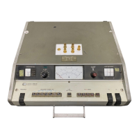
Model 4342A
Section III
Paragraphs 3-47 to 3-50
Measurements Requiring Corrections
Cd =*
D..oO.o..O. (eq. 3-7)
Where, Cd: distributed capacitance in
farads.
Cl : C dial reading (farads)
noted in step b.
fo: measurement frequency
(hertz) noted in step j.
f1:
measurement frequency
(hertz) noted in step d.
Note
If fo>fl, the eq. 3-7 is simplified
as follows:
Cd =
2
Cl
. . . . . . . . . . . (eq. 3-7)
3-47. Measuring Distributed Capacitance
(Approximate Method, CdllOpF).
3-48.
A distributed capacitance more than
approximately 1OpF may be measured with the
simplified procedure described below (this
procedure is useful for obtaining approximate
values of distributed capacitance with an
accuracy which serves practical purposes):
a.
Connect inductor sample to the meas-
urement COIL (HI and LO) terminals.
b. Set L/C dial control to approximately
50pF and AC dial control to OpF. Note
the C dial reading as Cr.
C. Depress a trial FREQUENCY RANGE button
and rotate FREQUENCY dial control to
search for the frequency at which
panel Q meter shows a maximum deflec-
tion. If no peak deflection can be
observed, change FREQUENCY RANGE set-
ting and repeat the procedure.
d.
Adjust FREQUENCY dial control for max-
imum panel Q meter deflection. Note
this frequency as fr.
e.
Change FREQUENCY dial setting to f2
equal to fl/n (n should be a selected
integer, e.g. 2 or 3).
f.
Adjust L/C dial and AC dial controls
for again obtaining maximum meter
deflection. Note the sum of C dial
and AC dial readings as Cz.
g-
Distributed capacitance is given by
the following equation. Substitute
measured values of Cl, Cp, fl and f2
in the equation:
Cd = w . . . . . .
. . (eq. 3-9)
fl
n =-
f2
Where, Cd:
Cl :
c2 :
f1:
f2:
distributed capacitance in
farads.
C dial reading (farads)
noted in step b.
C dial reading (farads)
noted in step f.
measurement frequency
(hertz) noted in step d.
measurement frequency
(hertz) given in step e.
Note
If fz is exactly one half of fl, then
Cd = ‘2 - 4c1
3
. . . . . . . . . . .
(eq. 3-10)
An average of several measurements
using different values of Cl will im-
prove the results of this measurement.
The best accuracy to be expected with
this method, however, is in the range
of +2pF.
3-49.
CORRECTION FOR Q.
3-50.
To use the indicated Q for the purpose
of calculating L and Rs (in determining the
actual equivalent circuit), it must be cor-
rected for the effects of the distributed
capacitance. The corrected Q and the Q value
measured by the Q meter can be obtained from
the following equation:
Qt = Qi
' +CCd . . . . . . . . . . .
(eq. 3-11)
Then,
Correction factor =
C + Cd
C
. . . . . . . . . . .
(eq. 3-12)
Where, Qt: corrected Q value.
Qi:
indicated Q value.
c:
sum of C and AC dial readings.
Cd:
distributed capacitance of
sample.
3-15

 Loading...